Showing posts sorted by relevance for query electrical symbols chart. Sort by date Show all posts
Wiring Diagram Symbols Chart

Wiring Diagram Symbols Chart

Basics 13 Valve Limit Switch Legend. Circuit diagrams provide the component layout in any circuit.


Electronic Schematic Symbols Electronic Schematics Electrical Symbols Electrical Wiring Diagram

HOW TO READ THE WIRING DIAGRAMS - Wire Colour Codes A-9 WIRE COLOUR CODES Wire colours are identified by the follow colour codes.

Wiring diagram symbols chart. Electrical Symbols With Images Electrical Symbols Electricity. Schottky diode is a diode with low voltage drop. Basics 14 AOV Schematic with Block included Basics 15 Wiring or Connection Diagram.

Symbols that represent the components in the circuit and also lines that stand for the links in between them. Unique Wiring Diagram Ac Blower Motor Electrical Circuit Diagram. A wiring diagram is a streamlined conventional photographic depiction of an electrical circuit.

Hvac Drawing Symbols Chart Wiring Wiring Circuit Diagram Source Electrical Diagram Symbols Wiring Components Symbols And Circuitry Of Air Conditioning Wiring Automotive Wiring Diagram Symbols Wiring Diagram Icons Daily Update Wiring Diagram Wiring Diagram Symbols Hvacr Example Wiring Diagram Hvac Drawing Symbols Chart Wiring. Code Wire colour Code Wire colour B Black P Pink BR Brown R Red G Green SB Sky blue GR Gray SI Silver L Blue V Violet LG Light green W White O Orange Y Yellow If a cable has two colours the first of the two colour code. Automotive electrical diagrams provide symbols that represent circuit component functions.

Heres a printable electrical symbols chart for your reference when preparing circuit diagrams. 1 Switch 2 Battery 3 Resistor and 4 Ground. For example a few basic symbols common to electrical schematics are shown as.

These electrical schematic symbols will help you to identify parts when working with an electrical schematic. Circuit diagrams can be created with thousands of possible shapes and icons and Lucidcharts circuit diagram maker has all the bells and whistles to ensure you have everything you need to create an industry-standard diagram. Wiring diagrams use simplified symbols to represent switches lights outlets etc.

Basics 10 480 V Pump Schematic. 21 Auto Industrial Electrical Wiring Diagram Symbols Electrical. Home Uncategorized Printable Chart of Electrical Symbols with their Meanings.

A wiring diagram is a sort of schematic which uses abstract pictorial icons to reveal all the interconnections of parts in a system. 107 rows Meter Symbols. Wiring diagrams use simplified symbols to represent switches lights outlets etc.

Electrical Wiring Diagram Electrical Drawing Symbols Electrical. Basics 11 MOV Schematic with Block included Basics 12 12-208 VAC Panel Diagram. One-line diagrams are used when information about a circuit is required but detail of the actual wire connections and operation of the circuit are not.

Gm Wiring Diagram Legend Electrical Circuit Diagram Electrical. Automotive electrical diagrams provide symbols that represent circuit component functions. Automotive manufacturers use block diagrams of individual circuits.

Basics 9 416 kV Pump Schematic. Single Phase Wiring Diagram. Basics 7 416 kV 3-Line Diagram.

WIRING CAPACITORS RESISTORS SEMICONDUCTORS Table 1 Standard Elementary Diagram Symbols contd Iron Core Air Core Auto Iron Core Air Core Current Dual Voltage Thermal Magnetic Single Phase 3-Phase Squirrel Cage 2-Phase 4-Wire Wound Rotor Armature Shunt Field show 4 loops Series Field show 3 loops Commutating or Compensating Field show 2 loops. Wiring Diagram Symbols Chart Diagram Diagram Design Electrical. Electronics symbols for schematics and wiring diagrams are mostly universal with a few of the symbols that may look different if reading other types of schematics.

Our circuit diagram symbol library is schematic and includes many icons commonly used by engineers. Here are charts to help you to identify symbols on electrical schematics. For example a few basic symbols common to electrical schematics are shown as.

Automotive Wiring Basic Symbols Common Symbols for Automotive Diagrams. Has very high resistance. Basics 8 AOV Elementary Block Diagram.

Electrical Circuit Symbols Electrical Wiring Diagram Electrical Outlets Electronic Engineering Electrical Engineering Control Engineering Radios Ac Wiring House Wiring. In order to represent the various components used in the diagram electrical symbols are used. Wiring representations are composed of 2 things.

Pnuematics Symbols Basic Hydraulic Symbols Group Picture. There are several other Electrical Wiring Symbols used in Residential and Commercial Wiring but the above list of symbols are the important ones. These Electrical and Electronic Circuit Symbols are generally used for drawing schematic diagram.

Here is the wiring symbol legend which is a detailed documentation of common symbols that are used in wiring diagrams home wiring plans and electrical wiring blueprints. One-Line Diagrams One-line diagram a diagram that uses single lines and graphic symbols to indicate the path and components of an electrical circuit. Describe the meaning of the G-W in diagram component R.

Saved by bookingritzcarlton wiring diagram database 9 Electrical Circuit Symbols Electrical Wiring Diagram Electrical Projects Electrical Engineering Current Electric Simple Circuit Diagram Design Electric Circuit Electronics Components. Standard Auto Wire Diagrams PDF Automotive Wiring Diagrams.

Schematic Diagram Legend

Schematic Diagram Legend

Here Is The 250w Rms Power Amplifier Circuit Called Legend Stage Master This Is The Previous Version Of Legend Stage Master Mk2 - Legend Stagemaster Amp Circuit Diagrams. Backup Valve Housing O-Ring --E14.


Bmw Wiring Diagram Symbols Car Engine Diagrams Electrical Symbols Electrical Circuit Diagram Electrical Wiring Diagram

Backup Valve Parts E10 30 on Schematic E11.

Schematic diagram legend. Wiring diagrams use special symbols to represent switches lights outlets and electrical equipment. 2 Arrow Syntaxsvg 531 443. Basics 11 MOV Schematic with Block included Basics 12 12-208 VAC Panel Diagram.

A schematic diagram is a blueprint of the electrical components within a system. TYPES OF WIRING DIAGRAMS There are three basic types of wiring diagrams used in the HVACR industrytoday. Zx9r e wiring dia.

This tutorial should turn you into a fully literate schematic reader. Wiring Diagram Symbols Electrical Wiring Symbol Legend-EET-2021. Understanding how to read and follow schematics is an important skill for any electronics engineer.

Aircraft Wiring Diagram Legend. Here is a standard wiring symbol legend featuring detailed documentation of wiring diagrams home wiring plans and common symbols used in electrical wiring blueprints. 1 Entity Syntaxsvg 567 602.

Basics 13 Valve Limit Switch Legend. 11 Schematic Diagram Of A Typical Uv Vis Spectrometer. See the picture to the right for an example of schematic diagram.

Scematic Diagram - Legend Stagemaster Amp Circuit Diagrams. Hvac Drawing Symbols Legend At Getdrawings Free. The following electronical parts are used in the cables and adaptors discussed on these pages.

Here is the wiring symbol legend which is a detailed documentation of common symbols that are used in wiring diagrams home wiring plans and electrical wiring blueprints. Click The Image To Open In Full Size - Legend Stagemaster Amp Circuit Diagrams. Legend Car FZ09 radiator mounting rule update 11121-1.

Images December 14 2019 Post a Comment. Legend car wiring diagram tech tips bando tnt ski doo u s cars international miniature automobiles ernie adams alarm schematic proper racecar principles 2005 smart full 600 race untitled t568 cat 6 schematics concatoracing acura ewd fuses relay harness legends sudlabo fr parts sdway motors brp grand. Well go over all of the fundamental schematic symbols.

Electrical Symbols on Wiring and Schematic Diagrams Appliances are what we in the bidness call electro-mechanical devices Oh yeah mmm hmm we professionals can throw around all kinda two-dollah words like that thats why. W Rms Power Amplifier Legend Stage. Schematic diagrams include a diagram notes and a legend.

Schematics are our map to designing building and troubleshooting circuits. Basic electrical symbol legend shows a collection of graphic notations used to represent various electrical and electronic devices such as cell battery resister heater etc. Products All-in-One Diagram Software.

Zx9r E1 Wiring Diagram Contributor posts 12366 registered 10403. 06 Appropriate constraint notationjpg 766 413. Media in category Diagram legends.

Basics 16 Wiring or Connection Diagram. It could be a mechanical PID electrical symbol legend or other types of diagram. Haynes Wiring Diagram Legend.

Among these youll find commonly used electrical drawings and schematics like circuit diagrams wiring diagrams electrical plans and block diagrams. Letro Legend LL105 In Ground Pool Cleaner Parts Diagram Letro Legend LL105 4 wheel pool cleaner. Duplex gfci 15 20 30 and 50amp receptacles.

Pride legend wiring diagram fresh wiring diagram for legend race car. The first and most common is the ladder diagram so called because it looks like the symbols that are used to represent the. Basics 17 Tray Conduit Layout Drawing.

Brp Ski Doo Legend Grand Touring 800 Se Sdi электрическая схема Manualzz. Schematic symbols building wiring diagram with pdf home recruitment house view 30 electrical hvac mechanical drawing design elements equipment software for registers drills and diffusers symbol of air condition in a circuit free diagrams. A legend or key that explains what the various symbols and abbreviations used in the schematic mean.

Use the legend to understand what each symbol on the circuit means. Wiring diagrams use simplified symbols to represent switches lights outlets etc. Pride Legend Scooter Wiring Diagram Diagram Wire.

The following 65 files are in this category out of 65 total. If youd like to buy parts for the cables and adaptors see the electronical parts page. Many schematic diagrams use a legend to aid in understanding.

Electrical Schematic Symbols Names And Identifications. Basics 14 AOV Schematic with Block included Basics 15 Wiring or Connection Diagram. A legend simply put is a chart with all of the symbols used in an individual diagram.

3-01a Symbols Used for IDEF3 Process Description Schematicsjpg 652. 6 Pole Wiring Diagram Electrical Symbols Wiring Diagram How To Read Auto Wiring Diagram Symbols Wiring Diagram Electrical Schematic Symbols Names And Identifications 3e61b Aircraft Intercom Wiring Diagram Wiring Resources Honda Wiring Symbols Data Wiring Diagram. Letro Legend LL105 In Ground Pool Cleaner Parts List Letro Legend Letro LL105 Pool Cleaner.

This is an invaluable tool because it simply is not possible to remember every single symbol used in our diagrams. Backup Valve Top Cover --E13. Basics 10 480 V Pump Schematic.

Wiring Diagram Relay Symbol

Wiring Diagram Relay Symbol

OVERLOAD RELAYS AC MOTORS DC MOTORS WIRING CAPACITORS RESISTORS SEMICONDUCTORS Table 1 Standard Elementary Diagram Symbols contd Iron Core Air Core Auto Iron Core Air Core Current Dual Voltage Thermal Magnetic Single Phase 3-Phase Squirrel Cage 2-Phase 4-Wire Wound Rotor Armature Shunt Field show 4 loops Series Field show 3 loops. Wiring and circuit diagrams use special symbols recognized by everyone who uses the drawings.


Instagram Electrical Schematic Symbols Electrical Symbols Electrical Wiring Diagram

The vector stencils library Switches and relays contains 58 symbols of electrical contacts switches relays circuit breakers selectors connectors disconnect devices switching circuits current regulators and thermostats for electrical devices.

Wiring diagram relay symbol. We discuss you Relay Logic Diagram Symbols with totally free downloading as well as cost-free reading online. When start relay and start capacitor are installed start thermistor is not used. The symbols on the drawings show how components like resistors capacitors inductors switches lamps acoustic devices measuring devices and other electrical.

Wiring Diagram comes with a number of easy to follow Wiring Diagram Guidelines. Electrical symbols electronic circuit symbols of schematic diagram resistor capacitor inductor relay switch wire ground diode led transistor power supply antenna lamp logic gates. Terminal 85 is given a negative power source and 86 is given a positive power source.

A normally open relay will switch power ON for a circuit when the coil is activated. 2s Lipo Battery Wiring Diagram. It shows the components of the circuit as simplified shapes and the.

Each circuit has two terminals. It presents the electric elements of the circuit as basic forms and likewise the connection and also power connections between those objects. A wiring diagram is a simplified traditional pictorial depiction of an electric circuit.

Relay Logic Circuits - SchematicSymbols A relay logic circuit is a schematic diagram which shows various components their connections inputs as well as outputs in a particular fashion. These directions will be. Wiring Diagram Symbols Circuit Relay Symbol Gm With Electronics circuit Electrical schematic symbols Electrical symbols.

Before wiring the relay first you should understand the wiring diagram of the relay. To Create a Wiring Diagram Symbol Four Pole Relay Wiring diagramsare graphical representations of connection information. A normally closed relay will switch power OFF for a circuit when the coil is activated.

5 pin relay wiring diagram 5 pin relay wiring diagram 5 pin relay wiring diagram 87a 5 pin relay wiring diagram driving lights every electric structure is composed of various unique components. The wiring diagram of an overload relay is shown below and the connections of an overload relay symbol may seem like two opposite question marks otherwise like s symbol. The coil circuits terminals are 85 and 86.

A relay has two circuits a coil and high amperage circuit. Thermostat symbol wiring diagramDesign elements. Dec 22 2018 - This Pin was discovered by M Bose.

Wiring Diagram Sony Explode Car Stereo Aux. Spdt Relay Wiring Diagram Wiring Diagrams Click 12 Volt Relay Wiring Diagram. Relay Wiring Diagram A wiring diagram is an common pictorial depiction of a complicated electric circuit.

The wiring diagramincludes a wiring diagram symbol for each device in the schematic withconnection data appearing next to it. Relay Logic Diagram Symbols that is composed by Anne Abt Study Group can be reviewed or downloaded and install through word ppt pdf kindle rar zip as well as txt. 48 - Incomplete-Sequence Relay 49 - Machine or Transformer Thermal Relay 50 - Instantaneous Overcurrent 51 - AC Time Overcurrent Relay 52 - AC Circuit Breaker 53 - Exciter or DC Generator Relay 54 - High-Speed DC Circuit Breaker 55 - Power Factor Relay 56 - Field Application Relay 59 - Overvoltage Relay 60 - Voltage or Current Balance Relay.

Dec 22 2018 - This Pin was discovered by M Bose. In electrical engineering a switch is an electrical. Central ac relay wiring diagram.

5 Pin Relay 5 pin relays provide 2 pins 85 86 to control the coil and 3 pins 30 87 87A which switch power between two circuits. Common electrical symbols this is not a definitive list of all symbols used in electrical identification but merely a. Discover and save your own Pins on Pinterest.

Wiring Diagram Symbol For Relay. Discover and save your own Pins on Pinterest. Alternatively wiring diagrams can usetables to display connection data in which.

Hydraulic pumps cylinders and motors. The wiring diagram of an overload relay is shown below and the connections of an overload relay symbol may seem like two opposite question marks otherwise like S symbol. Thermostat Symbol Wiring Diagram.

Thermal Overload Relay Wiring Diagram wiring diagram is a simplified welcome pictorial representation of an electrical circuitIt shows the components of the circuit as simplified shapes and the facility and signal. Addressable Led Strip Wiring Diagram. It really is meant to assist all the common person in creating a correct system.

Yamaha 250 Enticer Wiring Diagram. In relay logic circuits the contacts NO and NC are used to indicate Normally Open or Normally Close relay. Yamaha Pw50 Wiring Diagram Maret 167 Februari 181 Januari 171 2018 986 Desember 79 November 87.

K Symbol In Circuit Diagram

K Symbol In Circuit Diagram

If part of a component designation say component K204 it usually indicates a relay. The presentation of the interconnections between circuit components in the schematic diagram does not necessarily correspond to the physical arrangements in the finished device.


General Electrical Symbols Electrical Symbols Engineering Symbols Electricity

The standard circuit component symbols and circuit symbols are important for circuit schematic diagrams.

K symbol in circuit diagram. Basics 10 480 V Pump Schematic. Basics 7 416 kV 3-Line Diagram. Basics 14 AOV Schematic with Block included Basics 15 Wiring or Connection Diagram.

The zig-zag resistor symbol in their circuit diagrams and half use the simple rectangular symbol. Basics 9 416 kV Pump Schematic. The actual layout of the components is usually quite different from the circuit diagram.

Making a drawing of the connections to all the component parts in the circuits load makes it easier to understand how circuit components are connected. Examples of drawings of a simple circuit with a bulb cell and the switch. Standard Circuit Symbols For Circuit Schematic Diagrams.

Circuit Diagram Symbols Triangle. Perfectly for students engineers or electronic professionals to create circuit diagrams. Electrical plan symbols electrical one line symbols duplex receptacle a circuit designation b device type designation quadruplex receptacle.

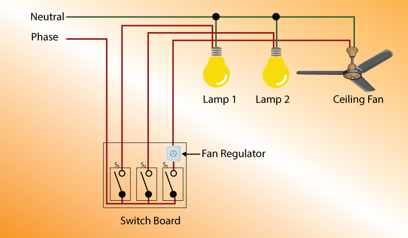
A circuit diagram or wiring diagram uses symbols to represent parts of a circuit. Figure 3 shows the Figure 1diagram redrawn in the house style of one of the most popular British electronics magazines Electronics Today International which uses the simple rectangle to represent a resistor and uses two black rectangles to. Examples of circuit symbols used in drawing circuits.

A pictorial circuit diagram uses simple images of components while a schematic diagram shows the components and interconnections of the circuit using standardized symbolic representations. Electrical circuit diagram symbols Electrical symbols are the most commonly used symbols in circuit diagramming. Circuit Diagram is a free application for making electronic circuit diagrams and exporting them as images.

Open ConceptDraw DIAGRAM new document page. Circuit symbols are used in circuit diagrams showing how a circuit is connected together. You can use the resistors and capacitors from our electrical drawing software.

How to Create an Electrical Diagram Using Integrated Circuit Library. Most of the industrial standard circuit items can be changed in the appearance style and color according to. From transistors to logic gates youll Electrical symbols are the most commonly used symbols in circuit diagramming.

Basics 13 Valve Limit Switch Legend. Click on an object and then click on the document at the place you want the object to be inserted. Use power source symbols to indicate alternating and direct currents in a circuit diagram.

Design circuits online in your browser or using the desktop application. Electrical and electronic circuits can be complicated. Several such symbols may be used in one diagram to represent the same reservoir.

For example a 10k resistor means 10000 ohms. A circuit diagram is a graphical representation of an electrical circuit. Most symbols used on a wiring diagram look like abstract versions of the real objects they represent.

Lucidchart has easy-to-use dialogs to let you switch the direction of the positive and negative charge icons as well as the orientation and the voltage label. K generally means 1000. Select libraries from Electrical Engineering section.

You can also make your circuit diagram stand out by adding a fill color with just one click. To build a circuit you need a different diagram showing the layout of the parts on breadboard for temporary circuits stripboard or printed circuit board. Other than standard use as a decimal point the 3 places I can think you may see a dot on a schematic are.

Circuit Diagram Signal Generator Symbol - The symbols represent electrical and electronic components. Unlike a block diagram or layout diagram a circuit. Basics 8 AOV Elementary Block Diagram.

Example of a simple circuit with the switch OFF. Basics 11 MOV Schematic with Block included Basics 12 12-208 VAC Panel Diagram. There are a few different ways to place an object into your drawing.

Amplifiers denoted by triangle shapes increase the output signal Electronic Circuit Symbols. Circuit Diagram Signal Generator Symbol A general term denoting any signal source. Look at each circuit diagram.

This page provides the most often used resistors and capacitors icons when drawing electrical schematics. The principles of signal modulation the block diagram of an am. Example of a simple circuit with the switch ON.

Example of a simple circuit with two bulbs with the switch ON. Circuit symbols are used in circuit schematic diagrams which show how a circuit is connected together electrically. Circuit Diagram Symbols Lucidchart Our circuit diagram symbol library is schematic and includes many icons commonly used by engineers.

Drawings for electronic circuits are called circuit diagrams.

Electronic Schematic Diagram Symbols

Electronic schematics represent the most detailed category of electronic drawings. Firstly quickly figure out which electrical symbol shall be used in the diagram.

Circuit Diagram Fuse Symbol Wiring Diagram Solid Panel A Solid Panel A Ilcovodelpirata It

In electronic circuits there are many electronic symbols that are used to represent or identify a basic electronic or electrical device.

Circuit Diagram Key

Circuit Diagram Key

Pc Keyboard Circuit Diagram. Component symbols in a circuit diagram.


House Wiring Diagram Symbols Pdf Electrical Symbols Electrical Circuit Diagram Symbols

Citroen Xsara wiring diagrams Key to circuits Diagram 1 Information for wiring diagrams Diagram 2 Starting charging and engine cooling fan Diagram 3 Engine cooling fan and air conditioning Diagram 4 Air conditioning Diagram 5 Pre-heating coolant levelseat belt warning lights Diagram 6 Warning lights and gauges Diagram 7 Lights on warning and.

Circuit diagram key. WORKING of Key-Hole Light Circuit. How can a circuit diagram be a key its just a load of funny squiggles isnt it. Some Circuit Diagram Rules.

To replace a conventional normal key switch without inserts keys. The following are general circuit diagram rules. The circuit includes two dc.

Circuit Diagrams Chart Answer Key. Resistors R2 R5 and R10 determine a voltage window within which the voltage applied to the junction of. In the given circuit diagram key K is switched on at t 0.

We do not need to carry a load key and do not worry about your keys. Sources two resistors and an ammeter. This Digital password door lock circuit diagram is a key code lock switch circuit type of electronic circuit.

Circuit Diagram Keypdf Where Stephen Curry ranks among the Warriors all-time greats in key statistical categories Heres a look at where he ranks among the franchises all-time greats in 10 key stats. This area is a growing library of the schematics wiring diagrams and technical photos. Everybody enables to check out online as well as download easily.

We supply Circuit Diagram Key by Torsten Werner Study Group in word txt pdf ppt kindle zip and also rar. It only requires under 5 minutes you will get just what you are seeking. The ratio of current i through the cell at t 0 to that at t will be.

There is a small problem in this point the buzzer will never stop fizzling because the output signal triggering the circuit again thought C1. All electronic components are represented by schematic symbols. It will move the output from pin 3 to pin 2.

Circuit Diagram Key Circuit Diagram Key Chapter 1. It causes the positive voltage at the input of IC1 in next step. Yes it is to the non-technical person but to a technical person a circuit or schematic diagram is very much a key to the equipment concerned.

The diagram to the right represents an electric circuit consisting of four resistors and a 12 volt battery. A Circuit Diagram Is The Key To Electrical Electronic Equipment And Systems Ideas About Wiring Diagram Symbol Key Typical Electrical Drawing Symbols And Conventions. But you can press the number code instead of unlockingkeys.

If it is dark over the LDR the resistance of LDR increases and if it is bright LDRs resistance decreases. Some of the worksheets displayed are simple circuits work circuits work circuit a circuit b circuits work r solving circuits work electricity. As you can see if we do not press the switch B it will not change any more of IC.

PLTW Gateway Magic of Electrons Circuit Diagrams Answer Key Page 1. In some cases a diagonal line may be used which is placed at 45 degrees. So the next switch that we must press to be switch B S2.

Key code lock switch circuit diagram. You could call the schematic diagram the coded key to the pulse of life in any piece of equipment big or small. Next when IC1 has the input is a positive voltage.

A Circuit Diagram is the key. As defense key in 4-1 defeat of Angels By Matt Kawahara The baseball jumped off Shohei Ohtanis bat at 1159 mph. Wiring View and Schematics Diagram.

Design circuits online in your browser or using the desktop application. Analog Electronic Key Schematic Circuit Diagram. Posted by Margaret Byrd Posted on October 18 2017.

The key K in circuit diagram shown in Fig. As defense key in 4-1 defeat of Angels By Matt Kawahara The baseball jumped off Shohei Ohtanis bat at. Circuit Diagram is a free application for making electronic circuit diagrams and exporting them as images.

Circuit Diagram Key Where Stephen Curry ranks among the Warriors all-time greats in key statistical categories Heres a look at where he ranks among the franchises all-time greats in 10 key stats. The emf of one source is ξ 1 and of the other is unknown. Showing top 8 worksheets in the category circuit diagrams.

Wires or lines in circuit diagrams are usually horizontal or vertical. A road sign that warns of a curve uses a symbol that is easy to interpret and recognizable by a driver. The internal resistance of the sources should be taken as zero.

Circuit diagram worksheet answer key. 90 can be either in position 1 or 2. After connecting the circuit as per the circuit diagram you can fix the circuit in the key-hole in any lock.

Quick and easy usb keyboard input kb5135 block diagram additional pc multimedia some keys on my laptop. The resistance of the resistors is also unknown. Road signs are good examples of recognizable symbols.

Here is the best location to get Circuit Diagram Key by Torsten Werner Study Group totally free. Next C5 discharges and everything is starting from beginning The AC voltage goes thought the buffer circuit of T2 to buzzer witch starts to fizzle. This circuit uses two comparators that are combined in what is called a window comparator ie.

Wiring Diagram Visio

Wiring Diagram Visio

Visio 2003 2007 Electrical Systems Drawing Part 2 Create Device. Use the Connector tool to connect electrical components or connector shapes.


Electrical And Electronic Engineering Forum Microsoft Visio For Perfect Diagrams And Flow Char Microsoft Visio Electronic Engineering Microsoft

Wiring Diagram Visio 2010 Wiring Diagram T2.

Wiring diagram visio. Visio 2010 Connectors And Connection Points Tutorial Wiring. With lanflow you can create great looking lan internet telecommunications and computer network diagrams with the minimum effort. Wiring Diagrams With Visio A wiring diagram is an quick visual representation of a circuits physical structure and electrical connections.

Ad Create Flowcharts Diagrams Easily With Visio For Your Small Business. Free Visio Stencil Electrical. Wiring Diagram Visio Unknown 1233 AM In just minutes you can plan and document a network show cabling and wiring and communicate flows and processes.

Wiring Diagrams Visio A wiring diagram is an easy visual representation of a circuits physical structure and electrical connections. How To use House Electrical Plan Software Wiring Diagram Floor. Visio Template Floor Plan Electrical Wiring.

Visio Wiring Diagram - Visio tips and tricks how to use microsoft visio to create diagrams rooms and organization charts duration. Diagram Microsoft Visio Wiring Full Version Hd Quality Freewirediagram Dolomitiducati It. Ad Make All Kinds Of Charts eg.

Time Lapse Circuit Diagram Visio Guy. Written By nash Thursday March 24 2016 Add Comment. Creating Electrical Schematics Microsoft Visio Version 2002 Inside Out.

Building Electrical Layout Visio. In the Define Shape Data dialog box click in each item and type or select a value. Computer Network Diagram Microsoft Visio Wiring Firewall Template Angle Png Pngwing.

Visio Template Floor Plan Electrical Wiring. Sorry for the sound did not have a proper headset for recording sound. Circuit Diagram Visio Alternative For Mac Windows And Linux.

Interconnecting wire routes may be shown. 8185 Car Wiring Diagram Visio Wiring Resources. Ad Make All Kinds Of Charts eg.

Basic Electrical Wiring Diagram House Simple Schematic Page 2 Line 17qq Com Materials Names Pdf In And Related Important. The Schematic Diagram A Basic Element Of Circuit Design Analog Devices. Free 21 Trial for Mac and PC.

The wireframe template in Visio Professional and Visio Plan 2 is designed for creating medium-fidelity mock-ups of software applications. Bl 3185 Wiring Harness Visio Diagram. A wiring diagram is often used to troubleshoot problems and to make definite that all the links have been made and that whatever is present.

Easily open view or make changes of Visio vsdx and vsd files. Architectural wiring diagrams be active the approximate locations and interconnections of receptacles lighting and permanent electrical services in a building. Create An Electrical Engineering Diagram Visio.

It describes how the electrical circuits are interrelated and can show exactly where different elements and fixtures are situated in relation to each other. Use the Connector tool. The template can be used for a wide range of software types such as applications for Windows the Internet and mobile devices.

Wrg 5568 Server Wiring Diagram. Minetest 0 3 Dfd Visio Png 1023 783 Data Flow Diagram. It describes how the electrical circuits are interrelated and can show exactly where distinctive elements and fixtures are positioned in relation to one another.

Block Diagram Visio 2010 Wiring. Visio Wiring Diagram wiring diagram is a simplified up to standard pictorial representation of an electrical circuit. Draw A Floor Technical Or Circuit Diagram Using Visio Or Google.

Floor Plans With Electrical Wirings. Flowchart Mind Map Gantt Chart Org Chart Floor Plan etc. Visio Wiring Diagram.

Select a shape right-click click Data and then click Define Shape Data. Vizio tv wiring diagram wiring diagrams. Visio Electrical Floor Plan.

It shows the components of the circuit as simplified shapes and the capacity and signal links amid the devices. Flowchart Mind Map Gantt Chart Org Chart Floor Plan etc. Netzoom visio stencils are vector drawings of equipment that scale and snap into place whenever connected.

Ad Create Flowcharts Diagrams Easily With Visio For Your Small Business. Visio Electrical Stencils Incredible Alternatives For Your Projects Like. Easily open view or make changes of Visio vsdx and vsd files.

Wiring Diagram In Visio

Wiring Diagram In Visio

Visio Wiring Diagram wiring diagram is a simplified up to standard pictorial representation of an electrical circuit. Visio 2010 Connectors And Connection Points Tutorial Wiring.


Pin By Mihail Aleksandrov On Q In 2021 Diagram Visio Network Diagram Stencils

The help section of Visio says it will open XLM files but Im unable to open them with Visio.

Wiring diagram in visio. Shapes can have data. Ad Easily open view or make changes of Visio vsdx and vsd files. Visio 2010 connectors and association points tutorial wiring.

Drag electrical component shapes onto the drawing page. Visio Template Floor Plan Electrical Wiring. You can change these settings at any time.

I need to make some adjustments to the diagram. The template can be used for a wide range of software types such as applications for Windows the Internet and mobile devices. Circuit Diagram Visio Alternative For Mac Windows And Linux.

Flowchart Mind Map Gantt Chart Org Chart Floor Plan etc. Written By nash Thursday March 24 2016 Add Comment. Ad Organise Complex Ideas Visually With Microsoft Visio For Your Business.

You can enter shape data and add new data to a shape. Ad Easily open view or make changes of Visio vsdx and vsd files. Create an electrical wiring diagram to display physical connections and physical layout of an electrical system or circuit.

It describes how the electrical circuits are interrelated and can show exactly where distinctive elements and fixtures are positioned in relation to one another. Visio Wiring Diagram. Wiring Diagrams Visio A wiring diagram is an easy visual representation of a circuits physical structure and electrical connections.

Wiring Diagrams With Visio A wiring diagram is an quick visual representation of a circuits physical structure and electrical connections. Make All Kinds Of Charts eg. How To use House Electrical Plan Software Wiring Diagram Floor.

Electrical symbols switches and relays electrical symbols. It describes how the electrical circuits are interrelated and can show exactly where different elements and fixtures are situated in relation to each other. Choose Metric Units or US Units and then click Create.

Vizio Tv Wiring Diagram wiring diagram is a simplified tolerable pictorial representation of an electrical circuit. Start by clicking the Dialogs stencil and dragging an Application form or a Dialog form onto the page. It shows the components of the circuit as simplified shapes and the power and signal associates in the company of the devices.

This video demonstrates the use of connectors and link points in creating a inborn wiring diagram it next shows how to consider images online to use as. I printed wiring diagram which Ive scanned with Acrobat pro. Create An Electrical Engineering Diagram Visio.

Qelectrotech An Open Source Wiring Diagram Tool Hackaday. Here is an electrical wiring diagram template available to download and use. Flowchart Mind Map Gantt Chart Org Chart Floor Plan etc.

An electrical engineering diagram visio creating schematics alternative converting to wiring time lapse circuit guy houseplan211 house plan symbols free stencil cad runs on pcb layout circuits how draw diagrams in stencils incredible templates microsoft computer template for drawer information drawing software the cloud open source. Visio Wiring Diagram - Visio tips and tricks how to use microsoft visio to create diagrams rooms and organization charts duration. Sorry for the sound did not have a proper headset for recording sound.

Make All Kinds Of Charts eg. The template opens an unscaled drawing page in portrait orientation. Draw A Floor Technical Or Circuit Diagram Using Visio Or Google.

Conceptualize visualize plan and document your audio video projects with visio shapes of an unequaled look technical accuracy and visual precision. Visio Electrical Floor Plan. What kind of format do I need to do this.

Software To Draw Electrical Circuit Diagram On Microsoft Visio. Floor Plans With Electrical Wirings. It shows the components of the circuit as simplified shapes and the capacity and signal links amid the devices.

The wireframe template is designed for creating medium-fidelity mock-ups of software applications. Ad Organise Complex Ideas Visually With Microsoft Visio For Your Business. Is there any way I can take an existing diagram and import or export it into Visio.

Netzoom visio stencils are vector drawings of equipment that scale and snap into place whenever connected.

Wiring Diagram Definition

Wiring Diagram Definition

Wiring diagram - a schematic drawing of the wiring of an electrical system. A diagram of the wires in an electrical installation or device showing the relationship between connections and components and usually also their physical arrangement.


Unique Basic Wiring 101 Diagram Wiringdiagram Diagramming Diagramm Visuals Visualisation Gr Electrical Circuit Diagram Diagram Electrical Wiring Diagram

Definition Cat5e Wiring.

Wiring diagram definition. Definition Of Wiring Diagram wiring diagram is a simplified enjoyable pictorial representation of an electrical circuit. A wiring diagram is a visual representation of components and wires related to an electrical connection. Schematic schematic drawing - diagram of an electrical or mechanical system.

Definition Of Wiring Diagram Electrical Wiring Diagram House for Define Wiring Diagram image size 512 X 385 px and to view image details please click the image. These diagrams are an effective way of showing how wires are interconnected with different components in a system. Wiktionary 000 0 votes Rate this definition.

Wiring and equipment on the wiring diagram are carefully laid out to show the approximate location of equipment in the circuit and. A part of the bodys physiology or neurology that determines or controls something such as a capability or disorder. Wiring diagram Noun A schematic representation of the components of an electrical device showing how electrical wiring must be connected.

Definition of wiring diagram. Wiring definition is the act of providing or using wire. Allowable wire and cable types and sizes are specified according to the circuit operating voltage and electric current capability with further restrictions on the environmental.

It shows the components of the circuit as simplified shapes and the skill and signal connections surrounded by the devices. A line drawing showing how the electrical connections of a device are made. Switch to new thesaurus.

Unlike a schematic its concerned with the connections between the different parts of a circuit or parts of an entire electrical system. Thesaurus Acronyms Encyclopedia Wikipedia. 85 - Carrier or Pilot-Wire Receiver Relay 86 - Lockout Relay 87 - Differential Protective Relay 89 - Line Switch 90 - Regulating Device 91 - Voltage Directional Relay 92 - Voltage and Power Directional Relay 94 - Tripping or Trip-Free Relay B Bus F Field G Ground or generator N Neutral T Transformer.

A wiring diagram is simply a pictorial representation of all the electrical connections in a specific circuit. We hope this article can help in finding the information you need. Here is a picture gallery about define wiring diagram complete with the description of the image please find the image you need.

A wiring diagram is a simple visual representation of the physical connections and physical layout of an electrical system or circuit. Define wiring diagram. A wiring diagram is the most common form of the electrical wiring diagram.

WIRING CAPACITORS RESISTORS SEMICONDUCTORS Table 1 Standard Elementary Diagram Symbols contd Iron Core Air Core Auto Iron Core Air Core Current Dual Voltage Thermal Magnetic Single Phase 3-Phase Squirrel Cage 2-Phase 4-Wire Wound Rotor Armature Shunt Field show 4 loops Series Field show 3 loops Commutating or Compensating Field show 2. Wiring Schematic Diagram Definition Wiring Diagram Image Free. This pictorial diagram shows us the physical links that are far.

Wiring is subject to safety standards for design and installation. Cat5e cable wiring diagram cat5 b wiring rj45 wiring -diagram usb rj45 cable wiring diagram definition catering to their financial needs cat5e wiring commercial cat5e wall jack wiring diagram cat5e wiring tools 7yupofintecforumdachde. It shows how the electrical wires are interconnected and can also show where fixtures and components may be connected to the system.

A structural or procedural diagram especially of an electrical or mechanical system. Wiring 1 Pha Diagram Full Size Of Starter Control Circuit Diagram. Evolution having made the basic computational units of language innate may have seen no need to replace every bit of learned information with innate wiring Steven Pinker.

Simple generator avr is dedicated to simple generator voltage regulationsimple generator wiring diagram the structure and working principle of generator usually consists of the stator rotor end cover and bearing componentsby the stator core stator line winding stand and fixed the parts of other. The wiring diagram shows different components in a circuit via different shapes and symbols. Electrical wiring is an electrical installation of cabling and associated devices such as switches distribution boards sockets and light fittings in a structure.

What Does Schematic Circuit Diagram Mean

A pictorial circuit diagram uses simple images of components while a schematic diagram shows the components and interconnections of the circuit using standardized symbolic representations. In a schematic circuit diagram the presentation of electrical components and wiring does not entirely correspond to the physical arrangements in the real device.


This Is The Schematic Diagram Of 30w Bridge Amplifier Circuit Based On Class Ab Audio Amplifier Chip Tda2040 Subwoofer Amplifier Amplifier Circuit Diagram

Schematic diagrams show components in their electrical sequence without regard for physical location.

What does schematic circuit diagram mean. A circuit diagram or a schematic diagram is a technical drawing of how to connect electronic components to get a certain function. From transistors to logic gates youll find icons that are modeled to international standards. After seeing a few circuit diagrams youll quickly learn how to distinguish the different symbols.

A schematic usually omits all details that are not relevant to the information the schematic is intended to convey and may add elements that aid. Schematic symbols are used to represent different electronic components and devices in circuit diagrams from wires to batteries and passive components to semiconductors logic circuits and highly complicated integrated circuits. A circuit diagram is a simplified conventional graphical representation of an electrical circuit.

A drawing showing the relation between the parts. Schematic Model is a diagram in model from. It is the adjective form the word schema.

Using the basic electrical symbols to draw a circuit diagram can show the manners in which the circuit components are placed. How To Read A Schematic Learn Sparkfun Com. The pictorial style circuit diagram would be used for a broader less technical audience.

The word schematic is defined as a diagram or a plan. Schematics are generally easier to read and understand than wiring diagrams. In these diagrams lines represent connecting wires while other elements like resistors lamps and switches are represented by standardized symbols called electrical schematic symbols.

Schematic drawing - diagram of an electrical or mechanical systemschematicdiagram - a drawing intended to explain how something works. How to read a schematic learn electric circuit diagrams lesson for understanding schematics technical symbols and an electrical diagram mean wiring everything you need. Schematic diagrams are used to troubleshoot and install control circuits.

Each electronic component has a symbol. Basics 10 480 V Pump Schematic. Schematics are our map to designing building and troubleshooting circuits.

Basics 13 Valve Limit Switch Legend. A schematic diagram refers to a specific type of circuit diagram that uses standard electricalelectronic symbols instead of pictures to demonstrate how a circuit or part of it works. A schematic circuit diagram represents the electrical system in the form of a picture that shows the main features or relationships but not the details.

A circuit diagram electrical diagram elementary diagram electronic schematic is a graphical representation of an electrical circuit. With the complete electrical schematic you can read the picture to know the physical connections and layout of an electric circuit. It is also defined as a technical diagram which explains how an electrical circuit functions.

Our circuit diagram symbol library is schematic and includes many icons commonly used by engineers. Both types show the connections between the devices including power and signal connections. Well go over all of the fundamental schematic symbols.

A schematic usually omits all details that are not relevant to the key information the schematic is intended to convey and may include oversimplified elements in order to make this essential meaning easier to grasp. Also called wiring diagrams or circuit diagrams these diagrams show how the different components of a circuit are connected. Basics 11 MOV Schematic with Block included Basics 12 12-208 VAC Panel Diagram.

Basics 17 Tray Conduit Layout Drawing. A schematic or schematic diagram is a representation of the elements of a system using abstract graphic symbols rather than realistic pictures. Our icons are grouped into different symbol families outlined below.

An example of a schematic plan or a schematic diagram is the flow chart in a textbook of science. A schematic style circuit diagram is used to give a visual representation of an electrical circuit to an electrician. Understanding how to read and follow schematics is an important skill for any electronics engineer.

These two different types of circuit diagrams are called pictorial using basic images or schematic style using industry standard symbols. A pictorial circuit diagram uses simple images of components while a schematic diagram shows the components of the circuit as simplified standard symbols. Below is a typical 3-wire motor control circuit using a typical momentary stop - start pushbutton station using a schematic diagram.

Basics 14 AOV Schematic with Block included Basics 15 Wiring or Connection Diagram. This enables anyone to read a circuit diagram and know what it does relatively quickly. Schematic diagrams are typically associated with electrical circuits.

This tutorial should turn you into a fully literate schematic reader. Basics 16 Wiring or Connection Diagram.

List Of Amplifier Circuit Symbol Ideas

List Of Amplifier Circuit Symbol Ideas


List Of Amplifier Circuit Symbol Ideas. The positive terminal of the battery is always at. The voltage that appears at the output, vout of the amplifier is the difference between.

Printable Chart of Electrical Symbols with their Meanings Science Struck
Printable Chart of Electrical Symbols with their Meanings Science Struck from sciencestruck.com

The voltage that appears at the output, vout of the amplifier is the difference between. I also suggest downloading electric symbols. Web battery circuit symbol.

A Schematic Diagram Or Flowchart Contains

A Schematic Diagram Or Flowchart Contains

With the help of a schematic flowchart show the break down of glucose in a cell to provide energy i in the presence of oxygen ii in the absence of oxygen. Create and coauthor professional-looking diagrams for effective decision making data visualization and process execution to help increase productivity across the business.


The Ultimate Flowchart Guide Flowchart Symbols Tutorials Examples

The food vacuole contains digestive enzymes with the help of which nutrients are digested.

A schematic diagram or flowchart contains. A block diagram is a specialized high-level flowchart used in engineering. In addition a simple flowchart diagram can be used as a schematic. A vacuole is usually found in all plant and fungal cells as well as some cells of protists animals and bacteria.

Basic Electrical Diagram is used to create schematic one-line and wiring diagrams and blue prints. Contains shapes for switches relays transmission paths semiconductors circuits and tubes. Each step in the sequence is noted within a diagram shape.

Steps are linked by connecting lines and directional arrows. Schematic drawings are also used in manufacturing during the design stage. Schematic diagrams only depict the significant components of a system though some details in the diagram may also be exaggerated or introduced to facilitate the understanding of the system.

Vacuole diagram. A schematic diagram is a picture that represents the components of a process device or other object using abstract often standardized symbols and lines. Its structure provides a high-level overview of major system components key process participants and important working relationships.

Visio and Microsoft 365 Visio is an innovative solution that helps you visualize data-connected business process flows with a host of integrated features that bring the power of Microsoft 365 to Visio. The food vacuole contains digestive enzymes with the help of which nutrients are digested. Create schematic one-line and wiring diagrams and blue prints.

However they can also involve steps that take place simultaneously especially if the diagram involves a complex system. Process Flow Diagrams are widely used by engineers in chemical and process engineering they allows to indicate the general flow of plant process streams and equipment helps to design the petroleum refineries petrochemical and chemical plants natural gas. Most of the flowchart symbols shown here are for use in very specific applications such as a data flow diagram used for computer programming.

With the help of labelled diagram describe an activity to show that the particles of matter are very small. Circuits and Logic Diagram is utilized to create annotated circuit and printed circuit board diagrams integrated circuit schematics digital and analog logic designs. View Basic Electrical Symbols.

Basic Electrical Diagram. There is a process flowchart swimlane flowchart workflow chart data flow diagram EPC diagram SDL diagram process map decision flowchart among others. Learn about different types of flowcharts and how theyre used.

Process flow diagrams of multiple process units within a large industrial plant will usually contain less detail and may be called block flow diagrams or schematic flow diagrams Process flow diagram. View Basic Electrical Examples. Flowcharts help you document processes map program algorithms plan projects make decisions and more.

There are ten types of Flowcharts. They help engineers understand how different parts fit together and interact to make the product work properly. As a verb diagram is to represent or indicate something using a diagram.

Use the following material that has been provided to you. It is used to. As nouns the difference between diagram and flowchart is that diagram is a plan drawing sketch or outline to show how something works or show the relationships between the parts of a whole while flowchart is.

Drawio can import vsdx Gliffy and Lucidchart files. Contains shapes for switches relays transmission paths semiconductors circuits and tubes. Quick Tips for Using Flowchart Symbols.

Unless you have specialized knowledge and your diagram is being developed for a peer group with similar knowledge its best to stick to basic flowchart symbols. In yeast cells the vacuole is a. Vacuole diagram.

A Flowchart is a graphically representation of the process algorithm or the step-by-step solution of the problem. It is used to design new systems or to describe and improve existing ones. This allows anyone to view the flowchart and logically follow the process from beginning to end.

A vacuole is usually found in all plant and fungal cells as well as some cells of protists animals and bacteria. You can use it as a flowchart maker network diagram software to create UML online as an ER diagram tool to design database schema to build BPMN online as a circuit diagram maker and more. In yeast cells the vacuole is a.

A flowchart is a visual representation of the sequence of steps and decisions needed to perform a process. Using the Flowcharts solution from the Diagrams area of ConceptDraw Solution Park you can easy and quickly design the Flowchart of any of these types. Schematic diagrams and flowcharts usually depict entities that involve one or more cause-and-effect sequences.

The positions of the components boxes arrows etc. A schematic representation of an ecosystem model In the example below rst the main components and arrows are drawn plotmat and the output of this function written in list pp. This often involves a set of steps or actions that take place sequentially.

Best Circuit Diagram Abbreviations 2023

Best Circuit Diagram Abbreviations 2023


Best Circuit Diagram Abbreviations 2023. Commonly used abbreviations used in. Web lexus ewd english electrical wiring diagram 2019 online auto repair software epc manual work service 2007 yaris manualzz abbreviations archtoolbox legend.

electrical abbreviations Gallery
electrical abbreviations Gallery from keywordteam.net

Ac or battery power rail for power circuit; This page is about the various possible meanings of the acronym,. These diagrams are used by the equipment.

Simple Circuit Diagram Software

Simple Circuit Diagram Software

PCB123 provides 500000 parts with great search functionality to access all the parts while drawing. SmartDraw Free Electrical Schematic Diagram Software.


Pin On Printed Circuit Board

Select from a huge library of vector schematic diagram symbols that scale easily without quality degradation.

Simple circuit diagram software. Visual Paradigm Online VP Online Free Edition is a FREE online diagramming software that supports Circuit Diagram UML wireframe ERD Organization Chart floor plan etc. Find info on MySearchExperts. It includes thousands of templates and examples to help you get started quickly.

You can do almost all your needs from design to build using PCB 123. It has a simple and friendly interface based on drag-and-drop gestures. It is mainly an electrical circuit design software that offers a large library of electrical components through which you can make simple and complex circuit designs.

Open an wiring diagram or circuit drawing templatenot just a blank screen. Design with our easy-to-use schematic editor. Free circuit drawing softwares list- PCB123 This is a free circuit drawing software from Sunstone.

Design circuits online in your browser or using the desktop application. Want a free Circuit Diagram software. Just play with tools and create circuit diagrams with professional Quality.

Circuit Diagram is a free application for making electronic circuit diagrams and exporting them as images. Edraw circuit diagram software is a cross-platform circuit diagram designing tool available on Mac Windows and Linux. It supports standard and custom symbol libraries.

With the drag-and-drop shapes and easily formatted connectors both novices and professionals can draw easy-to-read circuit diagrams in minutes. Launch CircuitLab or watch a quick demo video. Just drag and drop the required symbols.

Build and simulate circuits right in your browser. Analog digital circuit simulations in seconds. Ad Search for results at MySearchExperts.

It features a simple yet powerful editor that allows. If you are familiar with the MATLAB simulation software then most of the process is similar to that. The tool uses simple commands for shapes while the program automatically adjusts the position with the appropriate connections.

SmartDraw is a free software designed to create diagrams for electronic circuits. Heres how it works. Our circuit drawing software has many easy-to-use and powerful tools to let you effortlessly build any type of circuit diagram with dedicated symbol libraries.

With the built-in and industry-standard symbols in EdrawMax you can create basic circuit diagrams schematics diagrams wiring diagrams pictorial diagrams block diagrams etc. TinyCAD is a program for drawing electrical circuit diagrams commonly known as schematic drawings. TinyCAD is a free open source circuit design software for Windows.

It is also often used to draw one-line diagrams block diagrams and presentation drawings. It supports PCB layout programs with several netlist formats and can also produce SPICE simulation netlists. SmartDraws schematic diagram software is easy to use.

You can start creating your circuit diagram by using the tools required for the circuit diagram on the left side. Professional schematic PDFs wiring diagrams and plots. Launch it instantly with one click.

SmartDraw is the easiest circuit diagram maker on the market today. Plus all essential tools to create circuit design are also present in it.

Schematic Diagram Meaning In Bengali

Another word for Opposite of Meaning of Rhymes with Sentences with Find word forms Translate from English Translate to English Words With Friends Scrabble Crossword Codeword Words starting with Words ending. A voltage source is a two-terminal device which can maintain a fixed voltage.


Hvac Recruitment Hvac Maintenance Engineer Jobs Description Hvac 608 Certification Hvac Refrigeration And Air Conditioning Hvac Maintenance Hvac Supply

Plural for a schematic or visual representation of how something works or is built.

Schematic diagram meaning in bengali. A schematic or visual representation of how something works or is built. From scheme or schema. Ask in Bengali Forum.

Following is the schematic CRDi line diagram. Definitions and Meaning of diagram in English. It then calculates the precise quantity of fuel and timing of injection.

6 Basic Troubleshooting 1. Diagram exposition cluster diagram diagram konteksto. Schematic - Meaning in Bengali.

The traditional use has been for land surveying but they are also used extensively for building and infrastructure construction and some specialized applications such as meteorology and rocket launching. Plural for circuit diagram. The AC supply voltage is steeped by means of a step up transformer and further rectified by a bridge rectifier.

Most circuit problems are due to incorrect assembly always double check that your circuit exactly matches the drawing for it. Human translations with examples. The ripple-free high voltage DC is fed to a colpitts oscillator.

Also uterus starts preparation for another pregnancy. Diagram exposition cluster diagram diagram konteksto. Diagram exposition cluster diagram diagram konteksto.

It consists of a moveable telescope mounted so it can rotate. Contextual translation of schematic diagram into Tagalog. Day 1 uterus lining which is prepared for implantation starts to shed which lasts 3 to 5 days.

Once they have determined the best design then they have to figure out the best way to get all the parts and their. Human translations with examples. Real-world sources of electrical energy such as batteries and generators can be modeled for analysis.

Control Schematic Diagram Wiring Diagrams Lighting Meaning In Bengali Kannada Control Panel Schematic Drawing Panel Electrical Control Transparent Png Clipart. Common Rail Direct Injection. Contextual translation of venn diagram into Tagalog.

A matured egg follicle releases an egg from one of the ovaries. A schematic or schematic diagram is a representation of the elements of a system using abstract graphic symbols rather than realistic pictures. An ideal voltage source can maintain the fixed voltage independent of the load resistance or the output current.

The CRDi technology works in tandem with the engine ECU which gets inputs from various sensors. A particular ordered system or arrangement. A simplified line-drawing generally used by engineers and technicians to describe and understand how a system works at an abstract level.

Plural for a particular ordered system or arrangement. A voltage source is the dual of a current source. Mid-cycle phase this is the phase in which ovulation takes place ie day 13-17.

The oscillator circuit produces high frequency power and. Make a schematic or technical drawing of that shows interactions among variables or how something is constructed. How to say schematic diagram in Arabic.

A drawing showing the relation between the parts. A schematic usually omits all details that are not relevant to the key information the schematic is intended to convey and may include oversimplified elements in order to make this essential meaning easier to grasp. The ripple components are minimized by the use of LC filter.

A theodolite θiːˈɒdəlaɪt is a precision optical instrument for measuring angles between designated visible points in the horizontal and vertical planes. Human translations with examples. A drawing intended to explain how something works.

The schematic diagram reflects how computer engineers think about a motherboard. Contextual translation of diagram into Tagalog. However a real-world voltage source cannot supply unlimited current.

Schematic drawings often require the use of industry standard line-art symbols so they may be understood within industries.

Schematic Diagram Of 33/11kv Substation

Schematic Diagram Of 33/11kv Substation

The transformer and other equipment are. CONSTRUCTIONAL FEATURESOF 3311KV SHIRBHAVISANGOLA In.


Pin On Substation Design

REPORT ON 3311KV SUBSTATION 1.

Schematic diagram of 33/11kv substation. Six 11kV iii Transformers- a One 9MVA 33640695kV YY b Two 63MVA 3311kV Y Show the positions of. It promises a minimum daily power supply of 6- 8 hours. The two incoming feeders are.

It is a distribution sub-station placed overhead on a pole. Technical Specification for 3311KV ITPO Grid Substation in New Delhi INDEX SNo Description Page. The gang operated switch GO.

Etc of electric supply is called sub-station. 33 11kv substation layout electric cable may 7th 2018 - 33 11kv substation layout soltech 33 11kv substation layout drawing pdf 33 11kv substation indoor substation pdf layout diagram 132 kv substation 11kv Single Line Diagram Of 11kV Substation Circuit Globe May 8th 2018 - Substation Provides The Energy Supply For The Local Single Line. For instance 3311KV substation equipment will comprise digital multi-meters for various readings of currents and voltages.

Problem 5 Draw the single line diagram of a 3311kV substation having the following equipments- i Incoming line. This thesis report is prepared in according to the operation and maintenance procedure of 3311KV substation including emergency maintenance work. For substations contracted on turnkey basis the substation contractor shall be responsible for design material supply transport erection and installation and commissioning as well as.

Lets explained this scheme a little bit. 3311 kV substation single line diagram. Transformers above 8000 KVA shall have individual HV and LV circuit breakers.

Complete sets of schematic diagrams for control protection indication metering signalling. Fig i shows the layout of pole-mounted sub-station 2. Drawing 3311kv sub station single line diagram.

Equipment for Carrier Current. Voltage ac to a c freq. 11 Electrical Power System.

Draw the single line diagram of a 3311kV substation having the following equipments- i Incoming line. Drawing 3311kv sub station single line diagram. Components Of 3311 Kv Substation.

Substations AutoCAD 2 Auto cad 3311kv substation 2 66kv substation single line diagram 2 nu vot 2 draw a single line diagram mentioning one incoming line and two outgoing line 2 single line diagram of substion solved problem CAED 1 single line diagram of sub stations 1 single line diagram of indoor substation and accessories 1. The equipment of carrier current is installed in the substation for the purpose of communication supervisory control. 52 Single Line Diagram 27 53 Configuration of the Sub-Station 28 Chapter -6 3311 KV Sub-Station Equipme DPBS-1 61 Power Transformer.

1 Chapter 1 INTRODUCTION The assembly of apparatus used to change some characteristics eg. A substation generally have switching protection control equipment one or more transformers. Rural Electrification Board.

23 SINGLE LINE DIAGRAM DESCRIPTION 231 33 KV Side In Jaggampeta substation we observe two incoming feeders connected to 33 kv busbar from which they are stepped down to 11 kv using two power transformers. Switch consists of isolators connected in each phase of the 3. The present-day electrical power system is AC ie.

One 33kV ii Outgoing lines. Fig21Single line diagram of 3311kv sub station Jaggampeta. No 1 General Design Criteria 1 2 Civil Work 13 3 33kV GIS 42 4 11KV Auto-Switched Capacitor Bank 72 5 Structural Work 84 6 Outdoor Switchyard Material 91 7 Battery Chargers 103 8 Ni Cd Battery Bank 110.

SUBSTATION A Station is a subsidiary station of an electricity generation transmission distribution system where voltage is transformed to high to low or the reverse using transformers. Operation and Maintenance Of 3311 kV Power Substation. SCOPE OF WORK WATAMU 3311KV SUBSTATION.

Technical specification of 3311kV Sub-Station 10 16 MVA 4-36 q- Isolating valve shall be provided between the cooling radiators and the main tanks at the inlet and outlet of each radiators so as to permit removal of the radiator without draining the transformer completely. Rajiv Gandhi Grameen Vidyutikaran Yojana scheme was launched for rural electrification. Layout Design Of 33 11 Kv Substation downloads at Ebookinga com Download free xls.

It provides Free of cost service connection to all families Below Poverty Lines. 33 11kv substation layout Electric cable April 20th 2019 - 33 11kv substation layout drawing PDF electrical schematic drawing of 11kv indoor substation PDF layout diagram 132 kv substation 11kv substation PDF Layout Design Of 33 11 Kv Substation XLS. Electrical power is generated transmitted distributed in the form of the alternating current.

It includes Creation of atleast one 3311 kV or 6611 kV sub-station in each block. Whereas Fig ii shows the schematic connections. It is the cheapest form of substation as it does not involve any building work.

Figure 1 Typical single line diagram of a 1104 kV outdoor substation click to expand The 3-phase 3-wire 11 kV line is tapped and brought to the gang operating switch installed near the substation. One 33kV ii Outgoing lines. Six 11kV iii Transformers- a One 9MVA 33640695kV DYY b Two 63MVA 3311kV DY Show the positions of CTs PTs.

30 62 Parallel operation of transformer 34 63 Instrument Transformer 35 64 Definition of Switchgear 38 65 Insulator 44 66 Earthing 46 Chapter -7 33 KV Switching Substation Savar of DPBS-1.

Schematic Diagram Example With Explanation

Schematic Diagram Example With Explanation

Solar Panel Diagram With Explanation A typical block diagram of Solar PV system Download Scientific Diagram - To connect those strings of solar cells i used what is called a bus wire. Examples of electronic schematic diagrams.


What You Need To Know About Electronic Schematics Circuit Diagrams Explained In A Simple Way No Need Electronic Schematics Circuit Diagram Electronics Circuit

Power Quality For Audio Systems Power Supplies General.

Schematic diagram example with explanation. Schematic diagram depicting examples of the proportion demonstrating a an and its explanation describing sample meaning electrical drawings schematics overview difference between pictorial how to read learn selection procedure. There are many kinds of schematics diagram like a schematic map chemical engineering schematic electrical circuit schematic laptop schematic diagram pc schematic diagram LCD schematic diagram and much more. Cause and effect diagram example with explanation.

Posted by Margaret Byrd Posted on March 7 2021. For example when searching for capacitors I was able to find 19 different symbols. Below is a schematic diagram showing how cells in our body get energy from the digested food.

The authors that surround the four concepts shown in figure 4 are the most significant theorists of those that have provided the author with insight foundation and explanation for the design challenges experienced. ATP Adenosine triphosphate is a complex organic chemical that provides energy to drive many processes in living cells eg. All diagrams or a subset of diagrams for example diagrams related to a specific diagram template or diagrams that have not been updated for a particular number of days can be updated.

Each electronic component has a symbol. The current begins to drop as the battery starts to saturate. What is a circuit diagram.

A resistor The symbol for a resistor. Cause and effect diagram example with explanationExample fishbone diagram free fishbone diagram template 08 step iii the cause and effect diagram was adopted by dr w edwards deming as. Laptop Schematic Diagram-As like other schematics there are also schematic and block diagrams for laptops.

1 29 2019 more comprehensibly a schematic diagram is a simplified drawing that uses symbols and lines to convey important opinion guidance for example if you are taking the subway you may see a map showing you all the stations along a subway line but that map will not action all the roads and buildings you may pass along the way. Designed by Harry Beck in 1931 is an excellent example of a schematic diagram. Conceptual Framework Sample Of Schematic Diagram For Thesis.

Smps Circuit Diagram With Explanation Pdf - Diagram. For example if you are taking the subway you may see a map showing you all the stations along a subway line but that map will not show all the roads and buildings you may pass along the way. It enables the viewer to decide what trains to take to go from a specific station to another specific station with no claim to show where those stations are geometrically.

Since its an EE-centric schematic tool its pretty quick and easy to pull together circuit diagrams. More simply a schematic diagram is a simplified drawing that uses symbols and lines to convey important information. After seeing a few circuit diagrams youll quickly learn how to distinguish the different symbols.

A circuit diagram or a schematic diagram is a technical drawing of how to connect electronic components to get a certain function. Muscle contraction nerve impulse propagation and chemical synthesis. From this the actual operation of a piece of electronic equipment can be determined.

What is an example of a schematic diagram and its explanation. It shows the physical locations of Tube stations only to the degree that that information is necessary to understand the logic of the network. Plans dont show placement or scale just work and flow.

Figure 3 is an example of an electronic schematic diagram. Its easy for me to add or omit labels for components and find symbols that convey the appropriate level of detail for my diagram. Updates schematic diagrams stored in a schematic dataset or schematic folder.

Using the high low side driver ir2110 explanation and plenty of example circuits. Simple Schematic Diagram Example what is a schematic diagram. Electronic schematics use symbols for each component found in the electrical circuit even when small.

Semiconductors fall between conductors and insulators in terms.

Wiring Diagram Software Mac

Wiring Diagram Software Mac

With a wide range of wiring diagram symbols and built-in templates creating a wiring diagram has never been easier. A wiring diagram is a streamlined conventional photographic depiction of an electrical circuit.


Emergency Plan Sample Fire Emergency Plan In 2021 Workflow Diagram Emergency Plan Draw Diagram

Edraw wiringplan is a wiring diagram software that is designed to help engineers and technician make accurate and useful diagrams of a wiring project.

Wiring diagram software mac. ConceptDraw is a wiring diagram software that is available for the users on the Windows and Mac platform and is offered with a range of versions depending on price and functionality. It reveals the elements of the circuit as streamlined forms as well as the power as well as signal connections between the tools. Exhaustive Wiring Symbol Library.

It shows the components of the circuit as streamlined shapes as well as the power and also signal connections between the tools. Top Reasons SmartDraw is the Ideal Wiring Diagram Software. Creating uml diagram on mac with easy desktop software can be effortlessly.

Variety of mac wiring diagram software. A wiring diagram is a simplified conventional photographic representation of an electric circuit. With the drag-and-drop shapes and easily formatted connectors both novices and professionals can draw easy-to-read circuit diagrams.

Collection of mac wiring diagram software. With this software you can be able to achieve a lot more when it comes to creating designs for wiring. Wiring adalahwiring artinyawiring alarm mobilwiring among uswiring ac splitwiring atswiring ac mobilwiring alternatorwiring audio mobilwiring ats gensetdiagram alirdiagram adalahdiagram alir penelitiandiagram alir adalahdiagram activitydiagram arganddiagram alir prosesdiagram alir disebut juga dengandiagram aufbaudiagram aktivitassoftware adalahsoftware akuntansisoftware akuntansi gratissoftware as a servicesoftware.

Wiring diagram software for mac. Create Wiring Diagram with EdrawMax EdrawMax is a professional wiring diagram software focusing on helping you make neat accurate and high-quality wiring diagrams effortlessly and quickly. With this software you can be able to achieve a lot more when it comes to creating designs for wiring.

Conceptdraw is a wiring diagram software that is available for the users on the windows and mac platform and is offered with a range of versions depending on price and functionality. Electrical circuit diagrams Schematics Electrical Wiring Circuit schematics Digital circuits Wiring in buildings Electrical equipment House electrical plans Home cinema Satellite television Cable television Closed-circuit television. Edraw uml diagram software which has already done greatly on windows finally released its mac version and many features have been.

Gallery Of Mac Wiring Diagram software Sample. Free wiring diagram software mac wiring diagram is a simplified adequate pictorial representation of an electrical circuit it shows the components of the circuit as simplified shapes and the faculty and signal friends surrounded by the. Finish your electrical plans quicker with an Electrical Plan Software.

ConceptDraw is a fast way to draw. Free Wiring Diagram Software Edrawmax Online How To Use House Electrical Plan Software Technical Drawing And Symbols Free Home Wiring Diagram 15 Best Electrical Design Wiring Software For Mac Windows Of 2021. Dozens of wiring diagram examples let you be instantly productive.

Work with Other Programs with One Click Export your diagrams into Word Excel PowerPoint PDF SVG and transparent PNG Format with just 1. Simply select a wiring diagram template that is most similar to your wiring project and customize it to suit your needs. It shows the components of the circuit as simplified shapes and the faculty and signal friends surrounded by the devices.

The uml diagrams are widely used by software developers and software engineers. Even electrical wiring to be installed needs to undergo thorough planning. Free Wiring Diagram software Mac wiring diagram is a simplified adequate pictorial representation of an electrical circuit.

The choice of symbols and templates is sufficient although not great but ElectricDesign is a cheap and effective desktop tool for making electrical schematics. ConceptDraw is a wiring diagram software that is available for the users on the Windows and Mac platform and is offered with a range of versions depending on price and functionality. By linking shapes to data inserting hyperlinks and attachments this Mac diagram software will boost communication greatly.

ElectricDesign is perfect for creating prototype circuits or using as an automotive wiring diagram software on your Mac. House Electrical Plan Software works across any platform meaning you never have to worry about compatibility again. It supports pcb layout programs with several netlist formats and can also produce spice simulation netlists.

There also needs to be a diagram of where the switches notes detailing what wires to be used and so onThis can be done manually on blueprints but would need so a lot of effort and time. Circuit Diagram Software for Mac OS Edraw circuit diagram software is a cross-platform circuit diagram designing tool available on Mac Windows and Linux. EdrawMax is an all-in-one diagram software that makes it simple to create professional-looking flowcharts organizational charts network diagrams business presentations building plans mind maps science illustration genogram UML diagrams workflows program structures web design diagrams electrical engineering diagrams directional maps database diagrams and more.

Circuit Diagram Drawing Software Online

Circuit Diagram Drawing Software Online

Scheme-it Free Online Schematic and Diagramming Tool DigiKey Electronics. Flowchart Maker and Online Diagram Software.


Ask Make Software For Designing Circuits Make Arduino Projects Electronics Design Circuit Design

This tool can be accessed at free of cost.

Circuit diagram drawing software online. EasyEDA is a free and easy to use circuit design circuit simulator and pcb design that runs in your web browser. Find your search here. OmniGraffle Free Electrical Schematic Diagram Software OmniGraffle is a multipurpose drawing tool with powerful styling tools that can organize diagrams with just one click.

Page could not be loaded. SmartDraw is more than just easyit is also an incredibly powerful tool. VP Online features a handy electrical diagram tool that allows you to design electrical circuit devices components and interconnections with simplified standard symbols.

CircuitLab provides online in-browser tools for schematic capture and circuit simulation. Top 10 Best Circuit Diagram Makers 2021 My Chart Guide. Open an wiring diagram or circuit drawing templatenot just a blank screen.

SmartDraw is the easiest circuit diagram maker on the market today. Lucidchart is your circuit design software for drawing pictorial and schematic circuit diagrams. Scheme-it is a free online schematic drawing tool that will allow you to produce professional looking schematic diagrams add corresponding part numbers and share your schematic with others.

Ad Search for results at MySearchExperts. ZenitPCB is a free to use circuit design software. Drawio can import vsdx Gliffy and Lucidchart files.

Plus you can draw and discuss circuit diagram anywhere with an internet connection because VP Online is an online diagram software. You can use it as a flowchart maker network diagram software to create UML online as an ER diagram tool to design database schema to build BPMN online as a circuit diagram maker and more. Online Circuit Simulator Schematic Editor Circuitlab.

Heres how it works. Use our standard circuit symbols and intuitive editor to present systems with clarity. These tools allow students hobbyists and professional engineers to design and analyze analog and digital systems before ever building a prototype.

Whether your needs are in electrical circuit design mechanical design or component and industrial design SmartDraw can help you create all of your engineering schematics. Free Electronic Circuit Diagram Schematic Drawing Software. You can use it as a flowchart maker network diagram software to create UML online as an ER diagram tool to design database schema to build BPMN online as a circuit diagram maker and more.

This circuit maker online is one the best tool for drawing circuit diagrams. Logic Diagram Online 1966 Chevy 2 Wiring For Schematics. No matter you want an electrical diagram tool for teaching or for engineering purposes our online electrical diagram.

Flowchart Maker and Online Diagram Software. Hence SmartDraw also works as electrical drawing software. Sign up for free today.

Drawio can import vsdx Gliffy and Lucidchart files. You can use it as a flowchart maker network diagram software to create UML online as an ER diagram tool to design database schema to build BPMN online as a circuit diagram maker and more. Create a new design sheet to begin designing a circuit.

Similarly you can also use SmartDraw to create engineering drawings such as electrical diagrams. Free Circuit Diagram Maker Edrawmax Online. User-friendly tool even a newbie can create professional diagrams.

1Kicad Kicad is an. Create professional-looking diagrams in less time than youll spend with other programs. So many options are available to draw circuit either online or through software In my view having software and practicing on it makes you a perfect schematic designer.

AVSnap is a free software to draw a detailed circuit diagram. Drawio can import vsdx Gliffy and Lucidchart files. In this article i have listed some circuit diagram maker software make use of it.

Use this freeware to design electronic circuits with various circuit components. Circuit diagram or schematic capture and PCB printed circuit board design is very essential to design electronics. Add circuit symbols switches relays and more.

VP Onlines circuit diagram software gets you started quickly and finished fast through a rich set of circuit diagram shape a wide range of circuit diagram templates and an intuitive ciruit diagram editor. A black colored board with grid appears where you can place your components. Various options for exporting and Importing.

SmartDraw has more than 4500 different templates and CAD-like drawing abilities. This circuit diagram maker is. The best tool for drawing an electricalelectronic circuit diagrams and also flowcharts.

The Best Online Wiring and Circuit Diagram Software. Circuit Drawing At Getdrawings Free.

Schematic Diagram Example

Schematic Diagram Example

Sample Project Electrical Schematic Diagrams Eplan. Muscle contraction nerve i.


Kelsey Residence Jonathan Miller Diagram Arsitektur Gambar Arsitektur Ide

From this the actual operation of a piece of electronic equipment can be determined.

Schematic diagram example. Example A of an AC Schematic 22 Figure 12. Example A - DC Schematic of Relays Operating Switcher in Figure 15 26. Thesis conceptual framework concept diagram creately this is the conceptual framework of my thesis view and share this diagram and more in your device examples.

Figure 3 is an example of an electronic schematic diagram. The circular shape of the diagram would also indicate how the beginning of the film starts at the end in a continuous cycle or a loop. The scripts and table description for schema PM are at PM Schema.

Sample Project Electrical Schematic Diagrams Eplan. On it you can see some of the conventions used. Figure 3 Example of an Electronic Schematic Diagram A second type of electronic schematic diagram the pictorial layout diagram is actually not so much an electronic schematic as.

Thesis schematic diagram sample 2018. Examples of electronic schematic diagrams. Plans dont show placement or scale just work and flow.

Line Relay Symbol for Substation Single Line Diagram 18 Figure 10. We have to understand that researchers work to examine particular aspects of the. Simple Schematic Diagram Example what is a schematic diagram.

Diagram Mind Map Graphic Design. ATP Adenosine triphosphate is a complex organic chemical that provides energy to drive many processes in living cells eg. What Is A Process Flow Diagram Lucidchart.

They begin at a service allocation panel which has one neuter bus bar and 2 hot bus bars. Electronic schematics use symbols for each component found in the electrical circuit even when small. Figure 2 shows the symbols for such basic components as wires and Understanding and Using.

Schematic Diagrams Schematic diagrams document the connection points and construction methods of electrical and electronic circuits. 1 29 2019 more comprehensibly a schematic diagram is a simplified drawing that uses symbols and lines to convey important opinion guidance for example if you are taking the subway you may see a map showing you all the stations along a subway line but that map will not action all the roads and buildings you may pass along the way. More simply a schematic diagram is a simplified drawing that uses symbols and lines to convey important information.

Example B of an AC Schematic 23 Figure 13. Figure 3-2 Sample Schemas OE and PM illustrates schema PM. Block Diagram Learn About Block Diagrams See Examples.

Free Schematic Diagram Templates. A schematic diagram of a laser CVD system is shown in Figure 945. Have a trial for personal and commercial uses.

Illustrates sample schemas HR and OE and their relationship. Conceptual Framework Schematic Diagram Example In Research. Figure 3-1 Sample Schemas HR and OE.

Continuation of Example B of an AC Schematic 24 Figure 14. Experimental Design Uml Process Research Process Enterprise Architecture Framework Supply Chain Uml Diagrams Drugs Thesis Dependent Variable Quasi Experimental Stages Research Methodology Students Experiment Chapter. The source gas for example Si 2 H 6 is dissociated by a parallel laser beam ArF excimer laser and.

What better way to link our Schematic diagram to the film Raging Bull1980 than to make it in the shape of a bull ring with iconography possibly related to this as well such as a bulls head. A great platform for sharing schematic diagram templates. The scripts and table descriptions for these schemas are in section HR Schema and OE Schema respectively.

All templates are available to edit free in vector format. Figure 3 is an example of an electronic schematic diagram. Below is a schematic diagram showing how cells in our body get energy from the digested food.

Common Information for Example Of A Schematic Diagram In regard that the circuits that convey electricity to the diverse sectors are called as branch circuits. Figure 1shows a simple schematic diagram of a power sup-ply. Schematic Diagram Of A Combination Glass Electrode For Measuring Ph.

Example B of Single Line Diagram 21 Figure 11. For example if you are taking the subway you may see a map showing you all the stations along a subway line but that map will not show all the roads and buildings you may pass along the way. Synthesis Of Polyurethane Polymers Via Copper Azide Alkyne Click.

Today Hot Topic