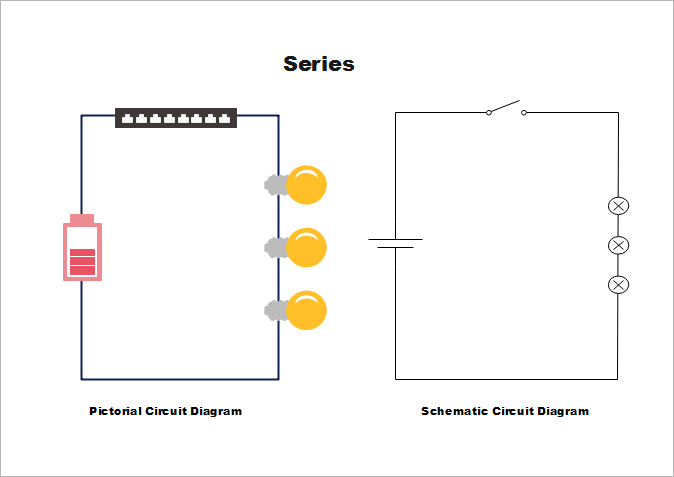
A pictorial circuit diagram uses simple images of components while a schematic diagram shows the components and interconnections of the circuit using standardized symbolic representations. In a schematic circuit diagram the presentation of electrical components and wiring does not entirely correspond to the physical arrangements in the real device.

This Is The Schematic Diagram Of 30w Bridge Amplifier Circuit Based On Class Ab Audio Amplifier Chip Tda2040 Subwoofer Amplifier Amplifier Circuit Diagram
Schematic diagrams show components in their electrical sequence without regard for physical location.
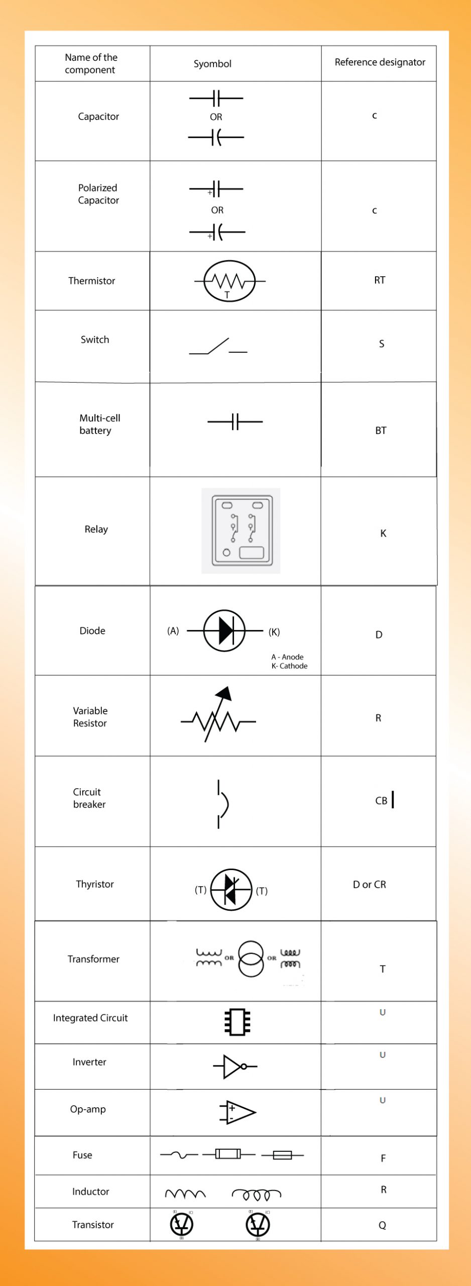
What does schematic circuit diagram mean. A circuit diagram or a schematic diagram is a technical drawing of how to connect electronic components to get a certain function. From transistors to logic gates youll find icons that are modeled to international standards. After seeing a few circuit diagrams youll quickly learn how to distinguish the different symbols.
A schematic usually omits all details that are not relevant to the information the schematic is intended to convey and may add elements that aid. Schematic symbols are used to represent different electronic components and devices in circuit diagrams from wires to batteries and passive components to semiconductors logic circuits and highly complicated integrated circuits. A circuit diagram is a simplified conventional graphical representation of an electrical circuit.
A drawing showing the relation between the parts. Schematic Model is a diagram in model from. It is the adjective form the word schema.
Using the basic electrical symbols to draw a circuit diagram can show the manners in which the circuit components are placed. How To Read A Schematic Learn Sparkfun Com. The pictorial style circuit diagram would be used for a broader less technical audience.
The word schematic is defined as a diagram or a plan. Schematics are generally easier to read and understand than wiring diagrams. In these diagrams lines represent connecting wires while other elements like resistors lamps and switches are represented by standardized symbols called electrical schematic symbols.
Schematic drawing - diagram of an electrical or mechanical systemschematicdiagram - a drawing intended to explain how something works. How to read a schematic learn electric circuit diagrams lesson for understanding schematics technical symbols and an electrical diagram mean wiring everything you need. Schematic diagrams are used to troubleshoot and install control circuits.
Each electronic component has a symbol. Basics 10 480 V Pump Schematic. Schematics are our map to designing building and troubleshooting circuits.
Basics 13 Valve Limit Switch Legend. A schematic diagram refers to a specific type of circuit diagram that uses standard electricalelectronic symbols instead of pictures to demonstrate how a circuit or part of it works. A schematic circuit diagram represents the electrical system in the form of a picture that shows the main features or relationships but not the details.
A circuit diagram electrical diagram elementary diagram electronic schematic is a graphical representation of an electrical circuit. With the complete electrical schematic you can read the picture to know the physical connections and layout of an electric circuit. It is also defined as a technical diagram which explains how an electrical circuit functions.
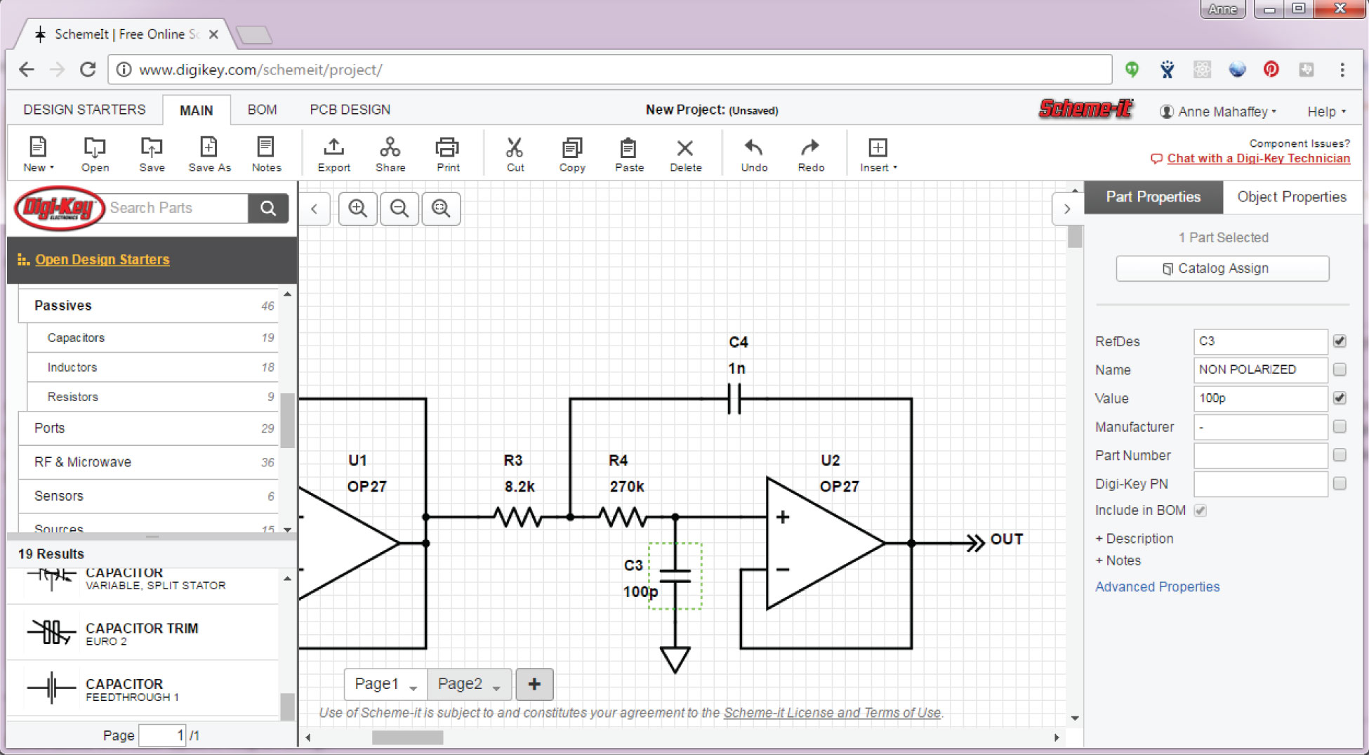
Our circuit diagram symbol library is schematic and includes many icons commonly used by engineers. Both types show the connections between the devices including power and signal connections. Well go over all of the fundamental schematic symbols.
A schematic usually omits all details that are not relevant to the key information the schematic is intended to convey and may include oversimplified elements in order to make this essential meaning easier to grasp. Also called wiring diagrams or circuit diagrams these diagrams show how the different components of a circuit are connected. Basics 11 MOV Schematic with Block included Basics 12 12-208 VAC Panel Diagram.
Basics 17 Tray Conduit Layout Drawing. A schematic or schematic diagram is a representation of the elements of a system using abstract graphic symbols rather than realistic pictures. Our icons are grouped into different symbol families outlined below.
An example of a schematic plan or a schematic diagram is the flow chart in a textbook of science. A schematic style circuit diagram is used to give a visual representation of an electrical circuit to an electrician. Understanding how to read and follow schematics is an important skill for any electronics engineer.
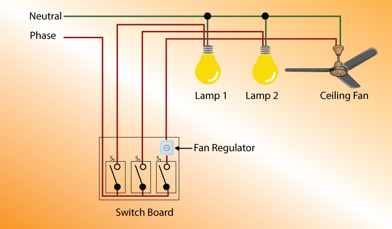
These two different types of circuit diagrams are called pictorial using basic images or schematic style using industry standard symbols. A pictorial circuit diagram uses simple images of components while a schematic diagram shows the components of the circuit as simplified standard symbols. Below is a typical 3-wire motor control circuit using a typical momentary stop - start pushbutton station using a schematic diagram.
Basics 14 AOV Schematic with Block included Basics 15 Wiring or Connection Diagram. This enables anyone to read a circuit diagram and know what it does relatively quickly. Schematic diagrams are typically associated with electrical circuits.
This tutorial should turn you into a fully literate schematic reader. Basics 16 Wiring or Connection Diagram.

Pin On Audio Circuitry
What Is The Meaning Of Schematic Diagram Sierra Circuits

Electrical Wiring Diagram And Electrical Circuit Diagram Difference Etechnog

What Is The Difference Between Schematic Diagram And Wiring Diagram For Electrical Connections Quora

Electrical Schematic Symbols Electrical Symbols Electrical Circuit Symbols Electrical Schematic Symbols
Difference Between Schematics And Circuit Diagrams

Electrical Wiring Diagrams For Air Conditioning Systems Part One Electrical Kn In 2021 Electrical Wiring Diagram Basic Electrical Wiring Electrical Circuit Diagram

Touch On And Off Switch Circuit Diagram And Working Circuit Diagram Electronics Circuit Electrical Projects
What Is The Meaning Of Schematic Diagram Sierra Circuits

How To Draw Electrical Diagrams And Wiring Diagrams In 2021 Electrical Diagram Circuit Diagram Electrical Circuit Diagram
The Schematic Diagram A Basic Element Of Circuit Design Analog Devices
Difference Between Schematics And Circuit Diagrams
What Does A Two Overlapping Circles Symbol Mean In An Electrical Schematic Diagram Electrical Engineering Stack Exchange

Definition Of Pictorial Diagram Diagram Definitions Chart

Electronic Schematic Symbols Electronic Schematics Electrical Symbols Electrical Wiring Diagram

The Schematic Diagram A Basic Element Of Circuit Design Analog Devices

Samsung Lcd Tv Circuit Schematic Circuit Diagram Tv Services Repair Manuals
What Is The Difference Between Schematic Diagram And Wiring Diagram For Electrical Connections Quora

Pin On Guitare


