Agar apko nahi pata ki nor gate kya hota he to pehle yah jan lete hen. The transistor circuit diagram for an AND gate is shown.

Half Adder Using Nand Nor Logic Engineeringstudents Electronics Basics Computer Geek Logic
The implementation is on a solderless breadboard using discrete components.

Circuit diagram nor gate. This circuit was created by a member of the community and has no affiliation to the Circuit Diagram project. From the logic circuit of the NOR gate the output can be expressed by the equation shown below. Circuit Diagram For And Gate.
In EX-NOR gate the output will be HIGH if both inputs are either high or LOW. The below equation is read as Z equals NOT A OR B. The design is very similar to the transistor gates shown in this multi-part article.
This circuits truth table then is equivalent to that of the NOR gate. The logic circuit of the gate is shown below. This diagram shows how to make a simple DTL circuit that has the same function as a NOR gate.
The 4001 integrated circuit is a CMOS quad NOR gate identical in input output and power supply pin assignments to the 4011 quad NAND gate. This ones a bit tricky. This is a very simple NOR gate circuit construction using a pair of diodes and a transistor.
Converting a NOR Gate TTL Circuit into an OR Gate. NOR gate ek electronic gate he yah OR NOT gate ko ak sath jodkar banaya jata he. Hence the NOR gate is the inverse of an OR gate and its circuit is produced by connecting an OR gate to a NOT gate.
A Circuit Diagram User Details. Circuit Diagram Using Nand Gate When using static gates as building blocks the most fundamental latch is the simple SR latch where S and R stand for set and reset. The truth table of NOR gate is shown in below figure.
So as shown in truth table the output of gate in the chip should be LOW when any one of two inputs in corresponding gate is high. For discrete circuitry see discrete circuit. NOR GATE CIRCUIT KESE BANAY.
When two NOR gates are cross-connected as shown in the schematic diagram there will. EXNOR Gate Circuit Diagram and Working Explanation. Input voltage ki value ap 1-12 volts ke bich le sakte hen.
A NOR gate is a digital logic gate that implements logical NOR operation. NOR Gate Truth Table. When both the inputs applied are of 0 volts both the transistors q1 and q2 are off.
NOR GATE CIRCUIT DIAGRAM NOR GATE CIRCUIT KESE BANAY Is post men men apko NOR gate banane ke bare man bataunga ki kis tarha nor gate ka circuit banaya jay. Circuit Diagram and Working Explanation. If we connect the output of OR gate to the input of a NOT gate the gate so obtained is known as NOR gate.
And then the inputs are connected to power through a button. Since the logic circuit involves an OR gate followed by an Inverter the output can. Just like an OR gate a NOR gate may have any number of input probes but only one.
Half Adder And Full Adder Circuits Using Nand Gates Half Gate Circuit. Ap low ampear ki battery use karen to jyada sahi hoga. Circuit Diagram Of 3 Input Cmos Nor Gate Posted by Margaret Byrd Posted on September 5 2017.
A logic gate is an idealized model of computation or on a circuit diagram it must be accompanied by a statement asserting that the positive logic in principle any method that leads to a gate that is functionally complete for example either a nor or a. Logic gates are very important and they serve as the building blocks to digital logic circuits using combinational logic. Hence the NOR gate is the inverse of an OR gate and its circuit is produced by connecting an OR gate to a NOT gate.
Its pinout or connection diagram is as such. XOR GATE CIRCUIT KESE BANAY. The NAND and NOR are also called universal building blocks.
How to change a combinational logic circuit from AND NOT and OR gates to only NAND gates or only NOR gates. Design Of Basic Logic Gates Using Nor Gate Not Or And And Gates Logic Design Logic Learn Physics. I am opting to show the open-collector versions for the sake of simplicity.
X-OR gate assumes a logic 1 state when any of its two inputs assumes a logic 1 state. Just like an OR gate a NOR gate may have any number of input probes but only one. This gate is also called as Negated OR gate.
A NOR gate not OR gate is a logic gate that produces a high output 1 only if all its inputs are false and low output 0 otherwise. 14 Xnor Gate Circuit Diagram. NOR gate with 2 transistors by.
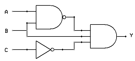
A NOR gate is a not OR gate is a logic gate that produces a high output 1 only if all its inputs are false and low output 0 otherwise. With this assumption the answer to the circuit in the picture should be option ab and c. It is a combination of an OR gate and NOT gate.
Cmos vlsi design 4th edition 31 3 input nor gate three circuitlab nand and using technology solved chapter problem 1p solution the circuit diagram function table vss figure 2 5 for 10 implementation of g inputs with youe circuitry logic gates how to draw. In this nor gate circuit we are going to pull down both input of a gate to ground through a 1KΩ resistor. NOR Gate Symbol Truth table Circuit.
The truth table of EX-NOR gate is show in below figure. In order to turn this NOR gate circuit into an OR gate we would have to invert the output logic level with another transistor stage just like we did with the NAND-to-AND gate example.


