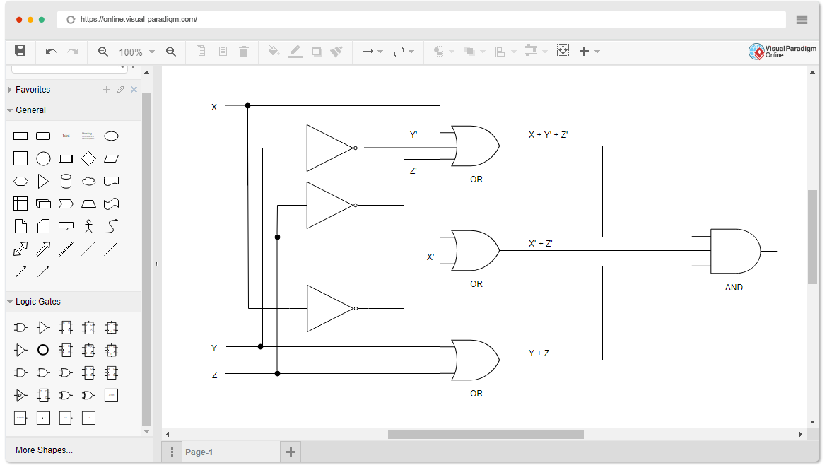
Design circuits online in your browser or using the desktop application. F a b c a b c.
Digital Logic Circuits Types Application Advantage And Disadvantage Engineer S Portal
Boolean Expression Diagrams BEDs.
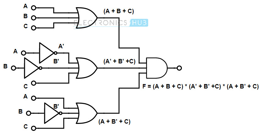
Circuit diagram generator from boolean expression. Firstly analyze the given expression. Through applying the laws the function becomes easy to solve. After that divide the given expression into small parts now if they are in product form then combine them with AND logic.
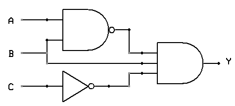
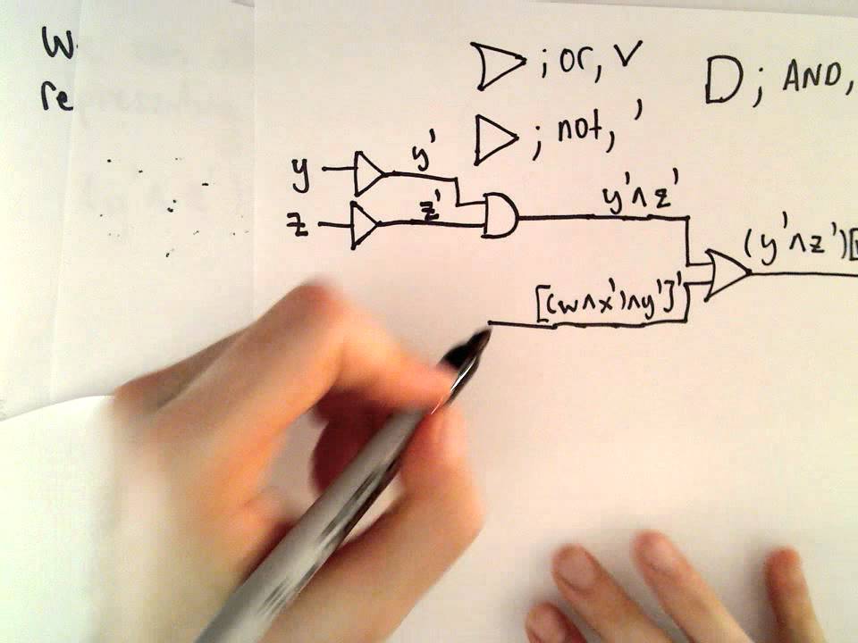
BE A. Q equals left bracket A or B right bracket and left bracket not C and A right bracket Q ABC A Start with the bracketed expression. Either starting from the inputs or starting from the outputs.
Start from the inputs. Boolean algebra has a set of laws that make the Boolean expression easy for logic circuits. Draw the equivalent logic circuit diagram for the Boolean expression using NOR gates only.
BorrowC AB BC in AC in. A b c asked Jan 29 2020 in Computer by lsganeshrathnam 91 points. This is obtained by extending the BDD representation with operator vertices.
Circuit Diagram is a free application for making electronic circuit diagrams and exporting them as images. One option is to identify the inputs and build the diagram up from there. Boolean expressions are simplified to build easy logic circuits.
Lets look at this Boolean expression. Boolean expression to logic diagram with example About Press Copyright Contact us Creators Advertise Developers Terms Privacy Policy Safety How YouTube works Test new features 2021. Draw a circuit diagram corresponding to the following Boolean expression.
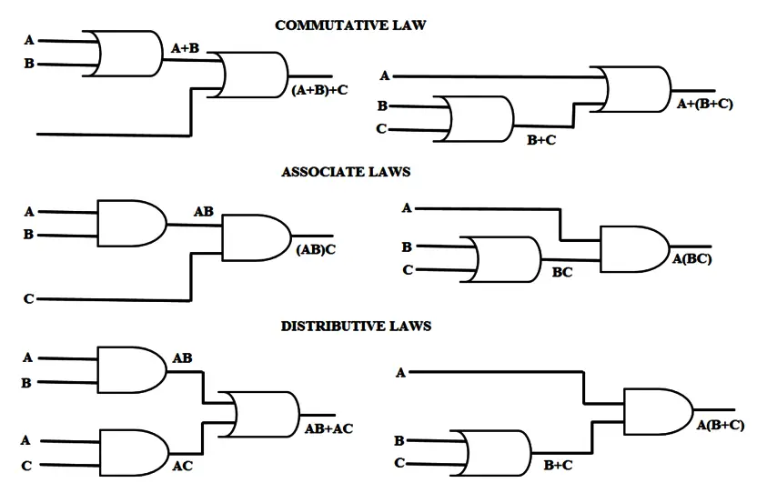
341 Digital Circuits and Their Relationship to Boolean Algebra 150 More complex Boolean expressions can be represented as combinations of AND OR and NOT gates resulting in a logic diagram that describes the entire expression. Laws of Boolean Algebra. According to this law.
How to Find the Boolean Expression from a Circuit DiagramIf you enjoyed this video please consider liking sharing and subscribingUdemy Courses Via My Webs. Boolean expression for three variables A B and a borrow C in generated in lower bit subtraction is represented as. In boolean expression to logic circuit converter first we should follow the given steps.
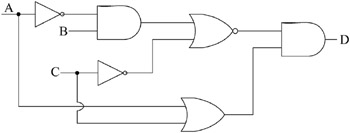
Converting circuit diagrams to boolean expressions About Press Copyright Contact us Creators Advertise Developers Terms Privacy Policy Safety How YouTube works Test new features 2021. Write the corresponding Boolean expression for this circuit using the letters A B and C to represent the status of relay coils CR1 CR2 and CR3 respectively. BE A B C Engineering Draw a circuit diagram corresponding to the following Boolean expression.
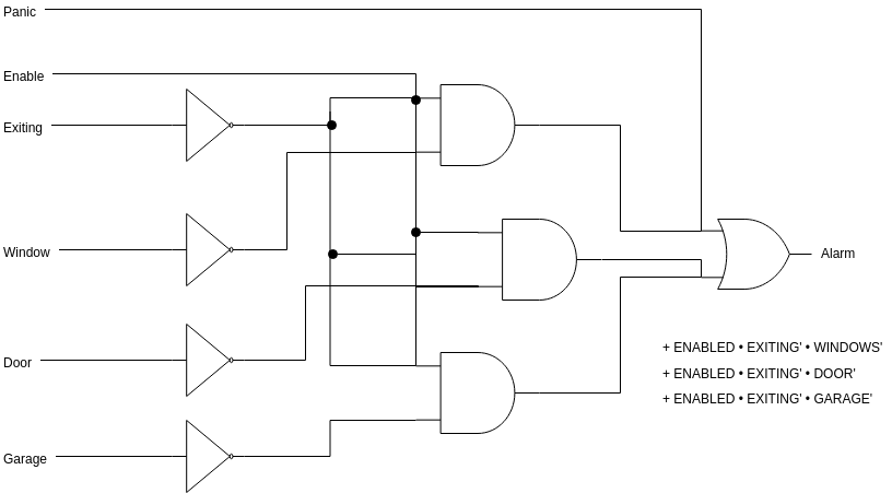
Converting boolean expressions to circuit digrams About Press Copyright Contact us Creators Advertise Developers Terms Privacy Policy Safety How YouTube works Test new features 2021 Google LLC. The solution to Part 1 worked but unfortunately it generated nuisance alarms whenever a technician powered any one of the supplies down for routine maintenance. When you learned about constructing truth tables you worked with this logical circuit diagram.
You can draw a circuit diagram for a Boolean expression. DifferenceD AꚚBꚚC in. Logic circuit simplification SOP and POS This is an online Karnaugh map generator that makes a kmap shows you how to group the terms shows the simplified Boolean equation and draws the circuit for up to 6 variables.
3 is a schematic diagram of a layout map generated in accordance with this invention for two boolean expressions based on four input variables. Definition 1 Boolean Expression Diagram A Boolean Expression Diagram BED is a directed. If they are in addition form then combine them with OR logic.
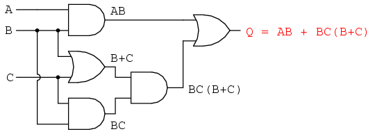
Here are the simplification rules. Circuit diagram There are two ways to approach writing an expression in Boolean algebra to represent this diagram. It also handles Dont cares.
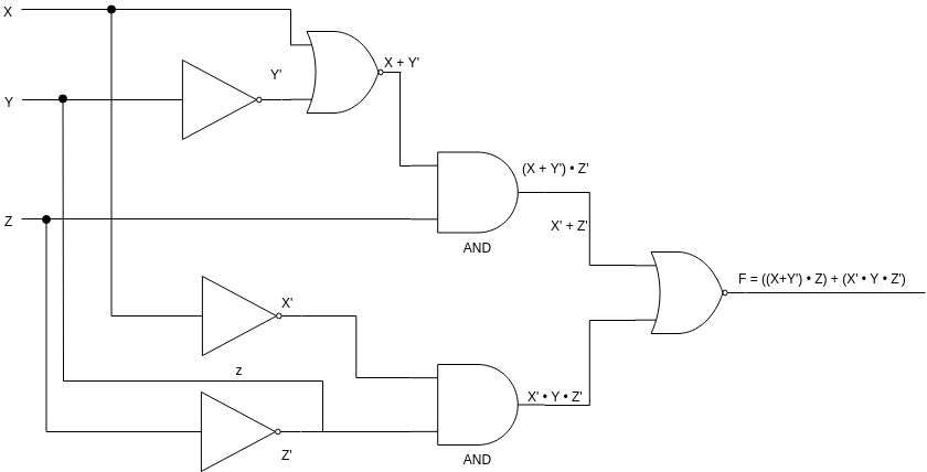
FIGURE 39 A Logic Diagram for Fx y z x yz 342 Integrated Circuits 151. BEDs can rep- resent any Boolean circuit 2 in linear space and still maintain many of the desirable properties of ROBDDs. 2A and 2B schematically illustrate best case and worst case permutations respectively of the input variables for a simple boolean expression.
A B B A. The Quine-McCluskey solver can be used for up to 6 variables if you prefer that.

Boolean Algebra Tutorial And Boolean Algebra Examples
7 2 Obtaining Boolean Expressions From Logic Diagrams Engineering360
Logic Diagram Software
Implementation Of Boolean Functions Using Logic Gates Nand Nor

Boolean Algebra And Logic Circuits
Logical Gates Drawing A Circuit That Corresponds To A Boolean Expression Part 4 Youtube
Logic And Boolean Expressions
7 6 Circuit Simplification Examples

Boolean Algebra Tutorial And Boolean Algebra Examples
Laws Of Boolean Algebra Using Ladder Logic Instrumentationtools

Boolean Algebra Tutorial And Boolean Algebra Examples
Logic Diagram Software
Teaching Digital Logic Fundamentals Logic Simplification Ni

Drawing Logic Circuits From Boolean Expressions Important Questions 3 Digital Electronics Youtube
Http Www Ee Ic Ac Uk Pcheung Teaching De1 Ee Lectures Lecture 2011 20 20logic 20gates 20and 20boolean 20 X2 Pdf

Combinational Logic Circuits Using Logic Gates
Using Circuitikz To Generate Logic Circuit Diagrams Tex Latex Stack Exchange

Logic Diagram Software
Http Www Ee Ic Ac Uk Pcheung Teaching De1 Ee Lectures Lecture 2011 20 20logic 20gates 20and 20boolean 20 X2 Pdf


