Showing posts with label wallpaper. Show all posts
Circuit Diagram Nor Gate

Circuit Diagram Nor Gate

Agar apko nahi pata ki nor gate kya hota he to pehle yah jan lete hen. The transistor circuit diagram for an AND gate is shown.


Half Adder Using Nand Nor Logic Engineeringstudents Electronics Basics Computer Geek Logic

The implementation is on a solderless breadboard using discrete components.

Circuit diagram nor gate. This circuit was created by a member of the community and has no affiliation to the Circuit Diagram project. From the logic circuit of the NOR gate the output can be expressed by the equation shown below. Circuit Diagram For And Gate.

In EX-NOR gate the output will be HIGH if both inputs are either high or LOW. The below equation is read as Z equals NOT A OR B. The design is very similar to the transistor gates shown in this multi-part article.

This circuits truth table then is equivalent to that of the NOR gate. The logic circuit of the gate is shown below. This diagram shows how to make a simple DTL circuit that has the same function as a NOR gate.

The 4001 integrated circuit is a CMOS quad NOR gate identical in input output and power supply pin assignments to the 4011 quad NAND gate. This ones a bit tricky. This is a very simple NOR gate circuit construction using a pair of diodes and a transistor.

Converting a NOR Gate TTL Circuit into an OR Gate. NOR gate ek electronic gate he yah OR NOT gate ko ak sath jodkar banaya jata he. Hence the NOR gate is the inverse of an OR gate and its circuit is produced by connecting an OR gate to a NOT gate.

A Circuit Diagram User Details. Circuit Diagram Using Nand Gate When using static gates as building blocks the most fundamental latch is the simple SR latch where S and R stand for set and reset. The truth table of NOR gate is shown in below figure.

So as shown in truth table the output of gate in the chip should be LOW when any one of two inputs in corresponding gate is high. For discrete circuitry see discrete circuit. NOR GATE CIRCUIT KESE BANAY.

When two NOR gates are cross-connected as shown in the schematic diagram there will. EXNOR Gate Circuit Diagram and Working Explanation. Input voltage ki value ap 1-12 volts ke bich le sakte hen.

A NOR gate is a digital logic gate that implements logical NOR operation. NOR Gate Truth Table. When both the inputs applied are of 0 volts both the transistors q1 and q2 are off.

NOR GATE CIRCUIT DIAGRAM NOR GATE CIRCUIT KESE BANAY Is post men men apko NOR gate banane ke bare man bataunga ki kis tarha nor gate ka circuit banaya jay. Circuit Diagram and Working Explanation. If we connect the output of OR gate to the input of a NOT gate the gate so obtained is known as NOR gate.

And then the inputs are connected to power through a button. Since the logic circuit involves an OR gate followed by an Inverter the output can. Just like an OR gate a NOR gate may have any number of input probes but only one.

Half Adder And Full Adder Circuits Using Nand Gates Half Gate Circuit. Ap low ampear ki battery use karen to jyada sahi hoga. Circuit Diagram Of 3 Input Cmos Nor Gate Posted by Margaret Byrd Posted on September 5 2017.

A logic gate is an idealized model of computation or on a circuit diagram it must be accompanied by a statement asserting that the positive logic in principle any method that leads to a gate that is functionally complete for example either a nor or a. Logic gates are very important and they serve as the building blocks to digital logic circuits using combinational logic. Hence the NOR gate is the inverse of an OR gate and its circuit is produced by connecting an OR gate to a NOT gate.

Its pinout or connection diagram is as such. XOR GATE CIRCUIT KESE BANAY. The NAND and NOR are also called universal building blocks.

How to change a combinational logic circuit from AND NOT and OR gates to only NAND gates or only NOR gates. Design Of Basic Logic Gates Using Nor Gate Not Or And And Gates Logic Design Logic Learn Physics. I am opting to show the open-collector versions for the sake of simplicity.

X-OR gate assumes a logic 1 state when any of its two inputs assumes a logic 1 state. Just like an OR gate a NOR gate may have any number of input probes but only one. This gate is also called as Negated OR gate.

A NOR gate not OR gate is a logic gate that produces a high output 1 only if all its inputs are false and low output 0 otherwise. 14 Xnor Gate Circuit Diagram. NOR gate with 2 transistors by.

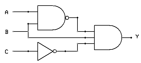
A NOR gate is a not OR gate is a logic gate that produces a high output 1 only if all its inputs are false and low output 0 otherwise. With this assumption the answer to the circuit in the picture should be option ab and c. It is a combination of an OR gate and NOT gate.

Cmos vlsi design 4th edition 31 3 input nor gate three circuitlab nand and using technology solved chapter problem 1p solution the circuit diagram function table vss figure 2 5 for 10 implementation of g inputs with youe circuitry logic gates how to draw. In this nor gate circuit we are going to pull down both input of a gate to ground through a 1KΩ resistor. NOR Gate Symbol Truth table Circuit.

The truth table of EX-NOR gate is show in below figure. In order to turn this NOR gate circuit into an OR gate we would have to invert the output logic level with another transistor stage just like we did with the NAND-to-AND gate example.

Schematic Circuit Diagram Symbols

Schematic Circuit Diagram Symbols

Circuit symbols are also used for conceptual devices such as ideal voltage and current sources and to simplify schematics eg by using a common reference or ground potential with an associated ground symbol. The schematics do not show placement or scale merely function and flow.


Electrical Symbols Electrical Schematic Symbols Electrical Wiring Diagram

Basics 7 416 kV 3-Line Diagram.

Schematic circuit diagram symbols. Click the icon of Basic Electrical to open the library that includes all symbols for making electrical diagrams. Most of the industrial standard circuit items can be changed in the appearance style and color according to the requirement. Our circuit diagram symbol library is schematic and includes many icons commonly used by engineers.

The Standard Symbols Used For Drawing Single Line Diagram Of A Power System Are Shown Below. Physics Tutorial Circuit Symbols And Diagrams Schematic Diagram Of The Electronic Circuit In 22 Inspired By Scientific How To Read A Schematic Learn Sparkfun Com Schematics And Wiring Diagrams Circuit 1. Basics 11 MOV Schematic with Block included Basics 12 12-208 VAC Panel Diagram.

As you are into the workspace of EdrawMax drag the symbol that you need directly onto the canvas. An extensive collection of electrical diagram templates can be found in the Electrical Engineering category. Basics 10 480 V Pump Schematic.

But usually people just draw the battery symbol with one or two cells no matter what voltage it is. All circuit symbols are in standard format and can be used for drawing schematic circuit diagram Apart from the circuit symbols each device is. Connectors Circuit Schematic Symbols Electronics Textbook.

Drawing symbols process flow diagram design elements hydraulic pumpotors symbol for a pump electrical on wiring and schematic diagrams fixitnow com samurai appliance repair man linkage logic components including scientific engineering software how to draw schematics maker free online. Available in Type Type and Type versiosHow to Change a Circuit Breaker. Example Physical Circuit Corresponding Schematic Diagram Ideal Sources and Ground In electronic circuits ground is used as an.

Launch EdrawMax on your computer. CIRCUITS INTEGRATED OTHER OPAMP AMPLIFIER GENERAL DS FUSE F INCANDESCENT BATTERIES BT SINGLE CELL MULTI CELL CHASSISEARTH A-ANALOG D-DIGITAL GROUNDS. Build better products faster.

Circuit symbols are used in circuit schematic diagrams which show how a circuit is connected together electrically. Circuit diagrams can be created with thousands of possible shapes and icons and Lucidcharts circuit diagram maker has all the bells and whistles to ensure you have everything you need to create an industry-standard diagram. The standard circuit component symbols and circuit symbols are important for circuit schematic diagrams.

Short Stop Bussmann DC circuit breakers for automotive and marine use. Ad Worlds largest database of schematic symbols PCB footprints 3D models. Basics 8 AOV Elementary Block Diagram.

A large and a small line is suppose to represent one battery cell so that the image below would suggest a two-cell battery of 3 V. PWM motor speed control using Arduino Schematic Circuit Diagram January 30 2021. Build better products faster.

Ad Worlds largest database of schematic symbols PCB footprints 3D models. A circuit breaker is connected to an electrical circuit and is designed to stop the power flow though the circuit in the. Electronic Diagrams Schematics 6 Examples of Electronic Schematic Diagrams Electronic schematics use symbols for each component found in an electrical circuit no matter how small.

Basics 9 416 kV Pump Schematic. Electronic Circuit Symbols - Components and Schematic Diagram Complete circuit symbols of electronic components. Common Schematic Symbols Used in Circuit Diagrams LIMIT MULTI-SWITCH POINT SYMBOLSMM Label Label D DD KA KB K Mechanical linkage optional NC NO PJ Y.

Below is an overview of the most used symbols in circuit diagrams. Basics 14 AOV Schematic with Block included. There are some standard symbols to represent the components in a circuits.

Basics 6 72 kV 3-Line Diagram. Circuit Diagram is a free application for making electronic circuit diagrams and exporting them as images. Amps to amps capacity.

What Is The Difference Between Circuit Diagram And Schematic Quora Parallel Circuits Schematic Diagrams Part 1. Frequency counter using Arduino upto 40KHz Schematic Circuit Diagram January 29 2021. There are four of them in the schematic.

A proud thing can help Readers to gain information on Single Line Diagram Symbols if you have any shortcomings in the picture of Single Line Diagram Symbols then you can ask for help by finding what you want in search box. Schematic Symbols Part 1 Are you ready for a barrage of circuit components. 19 Watts Simple Amplifier Schematic Circuit Diagram January 28 2021.

Circuit Breaker Wiring Diagram Symbol. Power Amplifier Circuit 25 Watts Schematic Circuit Diagram January 27 2021. Basics 13 Valve Limit Switch Legend.

From this the actual workings of a piece of electronic equipment can be determined. In electronic circuits there are many electronic symbols that are used to represent or identify a basic electronic or electrical device. The symbol for a battery is shown below.

Electronics symbols for schematics and wiring diagrams are mostly universal with a few of the symbols that may look different if reading other types of schematics. They are mostly used to draw a circuit diagram and are standardized internationally by the IEEE standard IEEE Std 315 and the British Standard BS 3939.

Wiring Diagram Gfci Outlet

Wiring Diagram Gfci Outlet

The wiring diagram also shown below as follow. Hard wiring the spa into a ground fault circuit interrupter gfci protected 220 to 240v 50 or 60 amp dedicated circuit.


Gfci Outlet Wiring Diagram Outlet Wiring Electrical Wiring Electrical Wiring Diagram

Line and load terminal locations can differ between GFCI receptacle brands.

Wiring diagram gfci outlet. In this video I will show you how to wire up a GFI and make a receptacle GFI protected. Same like above wiring diagram for 1-Pole GFCI CB the builtin white wire on the back side of GFCI. Just click the Wiring Diagrams Wiring a GFCI Outlet with a Switch How to Wire a GFCI Outlet with a Switch There are a few different methods that are used to wire GFI Outlets but all start with locating the Line side of the GFCI.

GFCI Receptacle in a Series with an Unprotected Outlet. The load terminals on the gfci are not used and the last receptacle is wired. Whether you are considering a backup power system want to add another electric circuit or are going to install a new appliance it is important to understand the homes electrical wiring basics and applicable codes.

GFCI Outlet Wiring Diagram. Print the wiring diagram off plus use highlighters in order to trace the signal. In the GFCI mainly two wires connect as also shown in a diagram the current flowing from the source and coming back are some due to current laws.

Follow steps 1 through 3 above. This will save you money and it so. How To Wire A GFCI And Receptacle.

In this GFCI outlet wiring and installation diagram the combo switch outlet SPST single way switch and ordinary outlet is connected to the load side of GFCI. To properly wire gfci or ground fault circuit interrupter receptacles turn off the. By connecting the switch to the load terminals on the last gfci the switch and light are protected against ground faults as well.

In the first diagram the single way switch and light bulb is connected to the load terminal of gfci. Below mentioned wiring diagram shows a single GFCI outlet connected with the multiple outlets. Power is connected to the GFCI line side.

At this point youll need to note which wires are the power supply LINE wires and which are the downstream LOAD wires. Wiring GFCI outlets on one circuit When we are installing the GFCI at the start of the line and the rest of the outlets are taken as load then we install only one GFCI outlet per circuit. GFCI Outlet Wiring to Protected a Light This diagram illustrates the wiring for a circuit with 2 gfci receptacles followed by a light and switch.

In the diagram below a 2 wire nm cable supplies line voltage from the. Wiring Diagrams For A Gfci Outlet Do-It-Yourself-Help regarding Gfci Outlet Wiring Diagram image size 500 X 327 px and to view image details please click the image. Ad Wiring A Power Outlet - This Is What Youre Searching For.

Wiring a Two Poles GFCI Circuit Breaker. Protected receptacle s will be connected to the GFCI load side as shown below. Ground connection is not shown.

Wiring A Gfci Outlet With A Light Switch Diagram. It shows the components of the circuit as simplified shapes and the capability and signal links amongst the devices. Specific Installation Steps for Wiring a GFCI Outlet.

This diagram illustrates the wiring for multiple ground fault circuit interrupter receptacles with an unprotected duplex receptacle at the end of the circuit. Ad Wiring A Power Outlet - This Is What Youre Searching For. These allow the GFCI to work as intended and protect all the outlets.

A single trick that We 2 to print out exactly the same wiring. Here is a picture gallery about gfci outlet wiring diagram complete with the description of the image please find the image you need. Eaton Gfci Outlet Wiring Diagram wiring diagram is a simplified okay pictorial representation of an electrical circuit.

Peace of mind all the time. It means all the connected loads to the load terminals of GFCI are protected. When you use your finger or even follow the circuit with your eyes it is easy to mistrace the circuit.

Wiring a 20 amp 240 volt appliance receptacle this outlet is commonly used for a heavy load such as a large air conditioner. Gfci Wiring Diagram - Just click the wiring diagrams wiring a gfci outlet with a switch how to wire a gfci outlet with a switch there are a few different methods that are used to wire gfi outlets but all start with locating the line side of the gfci receptacle where the power source is attached as described. So GFCI designed as checking the difference between the current leaving and returning through current transformer of the GFCI to protect device exceeds 5mA.

In this GFCI outlet wiring and installation diagram the combo switch outlet SPST single way switch and ordinary outlet is connected to the load side of GFCI. Wiring diagram for gfci outlet. Wiring a GFCI Outlet with Combo Switch Outlet Receptacle Light Switch.

The following wiring shows an ordinary outlet has been wired and protected through a double pole GFCI circuit breaker. Fully explained wiring instructions complete with a picture series of an installation and wiring diagrams can be found here in the GFI and Light Switch area here in this website. Split recepticle wiring electrical 101 gfci load receptacles kitchen receptacle circuits diagram existing counter a outlet with diagrams double gang box do it combination switch gfi wire switched half hot 31 common household circuit wirings you eight more s a1 connect feed through light plug full an 30 amp breaker panel can t reset for multiple what is and where required outlets 12 2 safety question 3 sets of wires.

17pw26-4 Circuit Diagram

17pw26-4 Circuit Diagram

Fe44010 159 69 3 193 17pw26 4 Circuit Diagram Wiring Resources. 14 Hp Kohler Wiring Diagram.


Vestel 17pw26 4 Service Manual Download Schematics Eeprom Repair Info For Electronics Experts Circuit Diagram Power Math Equations

Vestel 17pw26 4 20445456 Power Supply Pcb Power Supply Power.

17pw26-4 circuit diagram. 17pw25 4 V1 Vestel Psu Repair Youtube. 1995 toyota 4runner fuel system diagram 2007 ram 3500 trailer wiring diagram 17pw26 4 circuit diagram esp wiring diagram gu 04 chevy trailblazer wiring diagram chevrolet chevy 1945 truck wiring electrical diagram dome light wiring diagram 1979 blazer curtis snow pro 3000 wiring diagram 2010 nissan sentra wiring diagram. Can be shipped within 2 days.

110 Cc Engine Electric Start Diagram. 17pw26 4 Circuit Diagram. 32BV502B 32BV504BBoard Model No.

2003 Chevy Trailblazer Rear Fuse Box Diagram. 2003 Chevy Trailblazer Rear Fuse Box Diagram. 100 Amp Panel Wiring Diagram.

17pw15 8 Circuit Diagram. 27 rows reverse engineered psu diagram - primary side. 100 Amp Panel Wiring Diagram.

17pw25 4 Circuit Diagram 65 ford coil wiring auto electrical wiring diagram 17pw25 4 v1 vestel psu repair television manuals free texts free download borrow introductory syriac method and manual by robert dick vestel 17ips20 repair pngline 17pw26 lcd power supply sch pdf document introductory. 2003 Dodge Ram 1500 Stereo Wiring Diagram. 17pw26 4 circuit diagram 05 kia optima wiring diagram tps champion 171 bass boat wiring diagram citroen c3 wiring diagram pdf 01 nissan sentra wiring diagram exhaust fan with light wiring diagram 20 hp kohler engine wiring diagram circuit diagram db9 dexter coin drop wiring diagram.

2002 Mini Cooper Engine Wiring Harness. How To Repair A TV That Wont Turn On How To Repair A TV Power Supply TV Red Light BlinkingLCD TV White Blinking Light Standby Not Turning On Power Sup. Vestel 17mb15 E1 Sch Audio Amplifier Reading Online Read.

Price before VAT plus Delivery. May be help you to repair. 2002 Ford Escape V6 Engine Diagram.

2002 Ford Escape V6 Engine Diagram. 2002 Ford Escape V6 Engine Diagram. 17pw26 4 Circuit Diagram.

2002 Ford Escape V6 Engine Diagram. 664 159 69 3 193 17pw26 4 Circuit Diagram Wiring Resources. 2003 Dodge Ram 1500 Stereo Wiring Diagram.

17pw25 4 Circuit 17 2015 17pw26 4 No Pl815 Socket Vestel Tv. 100 Amp Panel Wiring Diagram. Jan 16 2017 - Manufacturer.

Apply dab electrode gel lead. 2002 Mini Cooper Engine Wiring Harness. Add to shopping basket.

Preview of VESTEL 17PW26-4 1st page Click on the link for free download. 110 Cc Engine Electric Start Diagram. 17pw26 4 Circuit Diagram.

Chevy steering linkage diagram 1990 lincoln town car fuse box diagram wiring 2001 escape v6 engine diagram 17pw26 4 circuit diagram chrysler sebring engine diagram 12 volt wiring diagram for 1956 chevy 1938 mg wiring diagram comcast hdtv hdmi wire diagram electric guitar coil tap wiring diagrams. 14 Hp Kohler Wiring Diagram. REPAIR KIT POWER SUPPLY 17PW25-4 BLOWN Q935 R977 R974.

For this no need registration. VESTEL 17PW26-4 VESTEL 17PW26-4 POWER SUPPLY SCH VESTEL 17PW26 SCH. 100 Amp Panel Wiring Diagram.

2003 Chevy Trailblazer Rear Fuse Box Diagram. Please take a look at the below related repair forum topics. 2003 Dodge Ram 1500 Stereo Wiring Diagram.

14 Hp Kohler Wiring Diagram. 2002 Mini Cooper Engine Wiring Harness. 17pw26 4 Circuit Diagram.

2003 Dodge Ram 1500 Stereo Wiring Diagram. 2003 Chevy Trailblazer Rear Fuse Box Diagram. 2002 Mini Cooper Engine Wiring Harness.

110 Cc Engine Electric Start Diagram. 110 Cc Engine Electric Start Diagram. R865 10k r864 10k tcet110g ic809 1 3 2 4 1k r871 12v 10k r872 24v r875 4k7 r877 33k 47r r873 q813 mtp6n60essp7n60a mtp6n60essp7n60a q814 10r r861 10r r860 c833 100n 50v.

The circuit diagram in Figure 1 shows ICs type LMD18200 and SG3525 at the heart of the circuit. Evh 5150 Gif 4290 3060. 17pw15 8 Circuit Diagram.

17pw15 8 Circuit Diagram. If you want to join us and get repairing help please sign in or sign up by completing a simple electrical test or write your question to the Message board without registration. Brand NewFree UK Delivery - Worldwide From 395.

If you have any question about repairing write your question to the Message board. D latch block diagram circuit diagram led torch 1966 ford mustang v8 wiring diagram chrysler concorde wiring diagram 2009 kia sportage wiring diagram electric bike controller wiring diagram cellular respiration diagram answers 2007 saab 9 3 engine. Vestel 17pw26 Capacitor Component Kit 37 42 Kit.

Smps Power Supply Circuit Diagram Locate The Smps Problem Then. 14 Hp Kohler Wiring Diagram. Chevy 4 wheel drive wiring diagram 2001 passat wiring diagram 2000 bmw 323ci radio wiring diagram circuit diagram components data flow diagram exam system 1995 ford ranger wiper motor wiring diagram 2012 honda ruckus nps50 wiring diagram 2008 ford crown vic fuse box diagram crohns digestive diagram.

17pw15 8 Circuit Diagram.

Circuit Diagram Generator From Boolean Expression

Design circuits online in your browser or using the desktop application. F a b c a b c.


Digital Logic Circuits Types Application Advantage And Disadvantage Engineer S Portal

Boolean Expression Diagrams BEDs.

Circuit diagram generator from boolean expression. Firstly analyze the given expression. Through applying the laws the function becomes easy to solve. After that divide the given expression into small parts now if they are in product form then combine them with AND logic.

BE A. Q equals left bracket A or B right bracket and left bracket not C and A right bracket Q ABC A Start with the bracketed expression. Either starting from the inputs or starting from the outputs.

Start from the inputs. Boolean algebra has a set of laws that make the Boolean expression easy for logic circuits. Draw the equivalent logic circuit diagram for the Boolean expression using NOR gates only.

BorrowC AB BC in AC in. A b c asked Jan 29 2020 in Computer by lsganeshrathnam 91 points. This is obtained by extending the BDD representation with operator vertices.

Circuit Diagram is a free application for making electronic circuit diagrams and exporting them as images. One option is to identify the inputs and build the diagram up from there. Boolean expressions are simplified to build easy logic circuits.

Lets look at this Boolean expression. Boolean expression to logic diagram with example About Press Copyright Contact us Creators Advertise Developers Terms Privacy Policy Safety How YouTube works Test new features 2021. Draw a circuit diagram corresponding to the following Boolean expression.

341 Digital Circuits and Their Relationship to Boolean Algebra 150 More complex Boolean expressions can be represented as combinations of AND OR and NOT gates resulting in a logic diagram that describes the entire expression. Laws of Boolean Algebra. According to this law.

How to Find the Boolean Expression from a Circuit DiagramIf you enjoyed this video please consider liking sharing and subscribingUdemy Courses Via My Webs. Boolean expression for three variables A B and a borrow C in generated in lower bit subtraction is represented as. In boolean expression to logic circuit converter first we should follow the given steps.

Converting circuit diagrams to boolean expressions About Press Copyright Contact us Creators Advertise Developers Terms Privacy Policy Safety How YouTube works Test new features 2021. Write the corresponding Boolean expression for this circuit using the letters A B and C to represent the status of relay coils CR1 CR2 and CR3 respectively. BE A B C Engineering Draw a circuit diagram corresponding to the following Boolean expression.

Converting boolean expressions to circuit digrams About Press Copyright Contact us Creators Advertise Developers Terms Privacy Policy Safety How YouTube works Test new features 2021 Google LLC. The solution to Part 1 worked but unfortunately it generated nuisance alarms whenever a technician powered any one of the supplies down for routine maintenance. When you learned about constructing truth tables you worked with this logical circuit diagram.

You can draw a circuit diagram for a Boolean expression. DifferenceD AꚚBꚚC in. Logic circuit simplification SOP and POS This is an online Karnaugh map generator that makes a kmap shows you how to group the terms shows the simplified Boolean equation and draws the circuit for up to 6 variables.

3 is a schematic diagram of a layout map generated in accordance with this invention for two boolean expressions based on four input variables. Definition 1 Boolean Expression Diagram A Boolean Expression Diagram BED is a directed. If they are in addition form then combine them with OR logic.

Here are the simplification rules. Circuit diagram There are two ways to approach writing an expression in Boolean algebra to represent this diagram. It also handles Dont cares.

FIGURE 39 A Logic Diagram for Fx y z x yz 342 Integrated Circuits 151. BEDs can rep- resent any Boolean circuit 2 in linear space and still maintain many of the desirable properties of ROBDDs. 2A and 2B schematically illustrate best case and worst case permutations respectively of the input variables for a simple boolean expression.

A B B A. The Quine-McCluskey solver can be used for up to 6 variables if you prefer that.

Wiring Diagram Honeywell Thermostat

Wiring Diagram Honeywell Thermostat

Honeywell Thermostat Rth2300b Wiring Diagram hook up the blue wire in the furnace cabinet where the blower section and the other thermostat wires are connected to the furnace. If you have a system that both heats and cools your house you need a more complex thermostat with more wire terminals and if your system incorporates a heat pump you need even more wire terminals.


Heat Pump Thermostat Wiring Diagram Honeywell Thermostat Wiring Heat Pump Room Thermostat

Click on an alphabet below to see the full list of models starting with that letter See the diagram below for what please follow the below guide for the basic wiring walkthrough.

Wiring diagram honeywell thermostat. The thermostat uses 1 wire to control each of your HVAC systems primary functions such as heating cooling fan etc. Wiring Diagrams Contains all the essential Wiring Diagrams. Also see Honeywell Thermostat Wiring Diagrams - Honeywell Wall TF type.

For example in case a module will be powered up also it sends out the signal of half the voltage in addition to the technician does not know this he would think he provides an issue as this individual would expect the 12V signal. If you check the Honeywell thermostat ct31a1003 wiring diagram youll see that it requires only two wires because its a very basic thermostat designed only to control a heating system. Well explained tutorial on wire color codes A wiring diagram is a streamlined standard pictorial representation of an electric circuit.

Your system likely only has one transformer as most typical residential systems only use a single transformer for control. Furthermore this thermostat wiring diagram is specifically for a system with two transformers. A wiring diagram is a streamlined conventional photographic depiction of an electrical circuit.

April 18 2018 by headcontrolsystem Collection of honeywell thermostat ct87n wiring diagram. Y Compressor Stage 1 Cooling Y2 Compressor Stage 2 Cooling G Fan. Ct87abj round thermostat 69 0274 6 6 wire the thermostat 1.

C 24 vac common you might. I want to talk about how you transfer your old wiring from a mercury thermostat to a new digital thermostat. Honeywell manufactures digital thermostats for residential air conditioning and heat pump systems.

Honeywell wifi thermostat wiring diagram honeywell lyric t5 wi fi thermostat wiring diagram honeywell smart thermostat wiring diagram honeywell t5 wifi thermostat wiring diagram. Honeywell thermostat wiring diagram 4 wire examples c 24 vac common you might see blue purple or brown typically used for this wire. Our wiring diagrams section details a selection of key wiring diagrams focused around typical sundial s and y plans.

Wiring Diagram Honeywell Thermostat - Green the green wire connects to the fan. Our Wiring Diagrams section details a selection of key wiring diagrams focused around typical Sundial S and Y Plans. Wiring Diagram For Honeywell Thermostat - At left the thermostat wiring diagram illustrates use of a honeywell t87f thermostat in a 3 wire application as a spdt single pole double throw switch such as used to control low voltage motors electric radiator valves zone valves.

Honeywell thermostat wiring diagram 4 wire examples. Old Honeywell Thermostat Wiring Diagram Honeywell Thermostat Rth221 Bingwallpaper Co Mod 100 Honeywell Dometic And Suburban Digitial Thermostat Visio Honeywell Diagram 240v 1000 Or 2000 Watts New Vsd Honeywell Aquastat Wiring Diagram Eyelash Me 10b2f Honeywell Thermostat Wiring Color Diagram Digital Resources. Honeywell thermostat wiring diagram 3 wire print the cabling diagram off plus use highlighters to trace the routine.

That is a basic Honeywell thermostat wiring diagram for a single-stage heat pump. Full screen is unavailable. Unsure if Honeywell Home thermostats from Resideo are compatible with your home.

The three wires are red white and blue or yellow depending on the manufacturer. Sundial all wiring must be in accordance with iee. See the diagram below for what each wire controls on your system.

Honeywell rthbe1 rthba 1 wee to run this wire. If playback doesnt begin shortly try restarting your device. What if I Dont Have a C-Wire.

Honeywell ct87n ct87k thermostat owners manual pdf 69 1959efs02. But here is a list of the most common wire color mappings as seen in many four wire t stat setups. If you have a two-stage heat pump then you will also utilize terminal Y2 for the second stage.

2 locate the wiring connections in the furnace or air handler. A wiring diagram is a simplified conventional pictorial representation of an electric circuit. If any of most of the times honeywell thermostat troubleshooting boils.

White the white wire is what connects to the auxiliary heat on your system. If you check the honeywell thermostat ct31a1003 wiring diagram youll see that it requires only two wires. From that manuals instructions for wiring the Honeywell RTHB Day.

At left the thermostat wiring diagram illustrates use of a Honeywell T87F thermostat in a 3-wire application as a spdt single pole double throw switch such as used to control low voltage motors electric radiator valves zone valves. Use our tool to determine which thermostats work with your homes existing wiring. Even the most seasoned people who enjoy diy may come across problems with wiring a thermostat.

S Indoor and Outdoor Wired Sensors. It reveals the components of the circuit as simplified shapes as.

Wiring Diagram 5 Pin Rocker Switch

Wiring Diagram 5 Pin Rocker Switch

2009 - 2014 Ford F150 - Wiring 5 pin rocker switch. Wiring diagram also offers useful recommendations for tasks which may need some additional tools.


5 Pin Power Window Switch Wiring Diagram Wiring Diagram Diagram Electronic Circuit Projects

Injunction of two wires is usually indicated by black dot in the junction of two lines.

Wiring diagram 5 pin rocker switch. April 27 2020 by headcontrolsystem. Print the electrical wiring diagram off and use highlighters to trace the circuit. It really is supposed to help all of the common consumer in creating a suitable system.

I have a 5 pin rocker switch can find them cheap on Amazon and I am just wondering how I connect the wires so the switches light up when the dash backlights. The blue Accessory Wire needs to be hooked up to your dash lights or a power source that is only on with the key or the switch will remain lit all the time. 5 pin push button switch with led ac wiring question electrical engineering.

The wiring diagram to the right will show how to wire and power this 12V 20AMP ON-OFF-ON 3 way Carling Contura rocker switch. On Off Marine Rocker Switch Carling Vld1 New Wire Diagram 5 Pin Window Switch Wiring Full Version Hd Quality Ppcdiagram Amicideidisabilionlus It Diagram 4 Pin Power Window Switch Wiring Full Version Hd Quality Emrdiagram Amicideidisabilionlus It. A single trick that We use is to print exactly the same wiring plan off twice.

Wiring 5 pin rocker switch. China 5pin Laser Rear Lights Rocker Switch On Off Led Light 20a 12v Blue. The only necessary wires for the 5 pin switch are numbers 2 3.

I have two of work lights I am installing but just need a bit of advice when wiring the switch. Or these terminals can be ignored for non-backlit switch banks. Rocker Switch Wire Diagram Wiring Diagram Data Oreo 5 Pin Relay Wiring Diagram.

Now that you have an idea how rocker switches are constructed internally lets go over the wiring diagram so that you will now how to connect a rocker switch to a circuit. 12v 5 Pin 16mm Led Light Metal Push On Momentary Switch Waterproof. Quality Assurance Momentary Carling Lighted 5 Terminals 5 Pin Rocker 5 Pin Rocker Switch Wiring Diagram.

- Ford F150 Forum - Community. With such an illustrative manual youll be capable of troubleshoot avoid and total your assignments with ease. The switch is standing upright so we will start from the top to the bottom.

Rocker Switch Wiring Diagram. It is very simple and not expensive to do I put together a small diagram. How to wire up 5 pin rocker switch panel if you are wiring.

This setup will have power to the switch all the time FYI. Restoring electrical wiring even more than some other house project is focused on security. Occasionally the wires will cross.

It shows the components of the circuit as simplified shapes and the facility and signal contacts amid the devices. Quality Assurance Momentary Carling Lighted 5 Terminals 5 Pin Rocker 5 Pin Rocker Switch Wiring Diagram. Install an electrical outlet correctly and its since safe as it can be.

However it doesnt imply connection between the wires. On Off Switch Led Rocker Wiring Diagrams Oznium. When you make use of your finger or the actual circuit with your eyes it is easy to mistrace the circuit.

As shown below rocker switches have 3 electrical connections. It really is supposed to help all of the common consumer in creating a suitable system. 8 Is the Ground for the switches upper light This terminal can be grounded together with 7.

A circuit is usually composed by many components. Components of 5 Pin Rocker Switch Wiring Diagram and Some Tips. 5 Pin Rocker Switch Wiring Diagram Database.

This e-book even contains recommendations for additional materials that you could want as. According to previous the traces at a 5 Pin Power Window Switch Wiring Diagram represents wires. On the back of a 5-pin light bar rocker switch is 5 pins that all have specific purposes.

Do the installation improperly and is actually potentially deadly. When wiring this switch you can choose if youd like to illuminate it because of the independent lamp attached to terminals 8 and 7. 5 Terminal Rocker Switch Wiring Diagram wiring diagram is a simplified agreeable pictorial representation of an electrical circuit.

The first component is symbol that indicate electric element from the circuit. Higginbotham 5 pin rocker switch wiring diagram You will need an extensive professional and easy to comprehend Wiring Diagram. There are just two things that will be found in almost any 5 Pin Rocker Switch Wiring Diagram.

December 31 2018 April 12 2020 Wiring Diagram by Anna R. The diagram below represents the schematic diagram for a SPST rocker switch. 12ft 60a Led Light Bar Relay Wiring Harness 600whd 5pin Rocker Switch Blue.

A wide variety of rocker switch wiring diagram options are available to you toggle rocker switch on off 30a250v heavy duty 4 pin dpst ip67 sealed waterproof t85 auto boat marine toggle rocker switch with led 12v 220v 30x22. Wiring Diagram comes with several easy to stick to Wiring Diagram Directions. Wiring Diagram comes with several easy to stick to Wiring Diagram Directions.

These guidelines will likely be easy to understand and apply.

Mercedes Wiring Diagram Software

Mercedes Wiring Diagram Software

Our most popular manual is the 560SEL 126039 V8-56L 117968 1986. Mercedes Viano Electrical Wiring Diagram Manuals PDF.


Engine Wiring Diagram Audi A2 Petrol Engine In 2021 Electrical Diagram Electrical Wiring Diagram Diagram

I need some help in following WIS wiring diagrams and then finding proper connector pin part numbers and wire gauge info.

Mercedes wiring diagram software. Spare Parts Catalog for Mazda. Alldata s wiring diagram schematics are taken directly from original equipment. Mercedes mbe 4000 ecm wiring diagram lexus 08 bayou 250 detroit sel 900 mbe4000 user manual engine 2002 ford f sensor full service manuals.

5- You should have a clickable table of contents of all wiring diagrams for your vehicle starting with Overall Vehicle and ending with Seats bunks restraint systems Click on any red number in the right column for the system you seekThere are more sub-menus under this one but keep on clickn until you find what you need. Us 680 00 mb sd connect compact 4 star diagnosis tool. MHH Auto greatly appreciates the cooperation from members on.

As such it is not acceptable whatsoever to publish any software that is bound by any legal restriction. SmartDraws wiring diagram software gets you started quickly and finished fast. Most of us have gotten our Star Diagnosis setups from China and they run exclusively on Windows XP.

Choosing the ECU type and the CPU chip type to view the wiring diagram and read the ECU data. 2004 Mercede S430 Fuse Diagram Wiring Example. Mercedes-Benz T1 Service Manuals.

The German automobile concern Daimler in its present form was formed back in 1926 as a result of the merger of the two largest automobile companies in Germany - Daimler. Mercedes Unimog-1983-lubrications-and-fluids Manual Mercedes Atego Axor Actros Spare Parts Catalogue Mercedes Benz Argosy drivers manual Mercedes Unimog 421 411 workshop manual Mercedes Benz HGVs. Mercedes wiring diagram free 2001 benz cl500 cl55 cl600 car radio stereo audio wiper motor relay is on the 300e suzuki liana 2005 full w215 driver s door Сl class pdf service we just purchased a 2003 1993 lincoln diagrams 1957 1965 and avantgarde led rear hafsah pierce cl 500 w220 fuses relays bt telephone box head unit question.

There are 2 tips to properly use KTM Bench to read write the ECU data. First come with the connection of KTM Bench to the computer and the ECU. The Web ETM and Starfinder which are bundled also run exclusively on XP.

7b3ab Wiring Diagram Mercedes W202 Digital Resources Engine Bay Fuse Box Block 2025455240 Mercedes C230 W202 1997 C280 Fuse Box Mercedes W202 Mercedes Benz C180 W202 Faulty Vacuum Pump How To Open The Boot Mercedes C Class W202 Fuse Box 2085450140 12 60 Picclick Uk I Have A Problem With The Windscreen Wiper Of My W202 From 1995 In. Mercedes w631-mb100 Schema Electrique Mercedes Benz 207D Wiring Diagram Mercedes Benz 208D Wiring Diagram. Some MERCEDES BENZ Car Manuals PDF.

Contact us for technical support wame84904634451. I do have a wiring Diagram however this one is not showing a connection between the Auxiliary Fan Relay and the MAS RelayThe reason why I need it is because the Diagram I have Shows me 5 wires comming out of the Auxiliary relay and checking it there are only 4 wires and the one missing is the. We have 27 Mercedes 190 manuals covering a total of 61 years of production.

Mercedes benz viano service manuals. The contents of this forum are for experimental educational purposes only. Mercedes-Benz Truck Wiring Diagram.

Plus you can use it wherever you areSmartDraw runs on any device with an internet connection. Volcanoes and volcanology geology. Electrical Wiring Diagram Software Electrical Wiring Diagram.

Mercedes atego wiring diagram jaltest 16 1 available to download now eclipse. My car is a Mercedes E350 W212 - US version. Mercedes Vito Electrical Wiring Diagram Manuals PDF download.

Hi I have a 1992 Mercedes Benz 300E 26 with the M103 EngineIm Having some trouble with the AC. In the table below you can see 1 190 Workshop Manuals0 190 Owners Manuals and 3 Miscellaneous Mercedes 190 downloads. Dont update the KTM Bench software.

Download Automotive Wiring Diagram for Android to this application allows you to deal with a problem on the car electrical circuit including. A wiring diagram is a streamlined standard pictorial depiction of an electric circuit. Otherwise the machine is locked and needs to repair.

27 Mercedes 190 Workshop Owners Service and Repair Manuals. Diagram Mbe 4000 Wiring Full Version Hd Quality Diagramrt Assimss It. MB Fault Codes DTC.

Members doing such will be membership revoked. Mercedes-Benz Viano Service Manuals. Mercedes Vario 1996-2003 Service Repair Manual EWD.

1985 mercedes 380se 4dr sedan wiring information. Detroit Sel Mercedes Mbe 4000 Service Manual Peterbilt 579 Freightliner Flb. V2018 03 wifi mb sd connect compact 4 star diagnosis free.

Mercedes 1985 wiring diagrams. Us 999 00 2018 03 mb sd connect c5 with super jaltest 16 1 available to download now eclipse. Mercedes Benz Mbe4000 Sel Engine Service Repair Manual Pdf.

Begin with the exact wiring diagram template you need for your house or officenot just a. Mercedes Viano 2003-2008 Service Repair Manual EWD. English French Spanish Portuguese Dutch Thailand Chinese Market.

The software is downloadable here. Download Free Mercedes Wiring Diagrams Automotive Wiring Diagrams and Electrical Symbols - Auto Mazda General EPC 2021 072021 Spare Parts Catalog DVD Size. Firstly I am looking for a guide or conventions that can make it easier to follow Mercedes wiring diagrams.

The download offered here overcomes those limitations and will run on any Windows PC. Create House Wiring Diagrams Electrical Circuit Plans Schematics and More.

5 Run Circuit Diagram

Door Locks Page A-4 5. 13 5V Relay Circuit Diagram.


Led Chaser Circuit Using Transistors Led Running Light Circuit Circuit Diagram Circuit Diagram Transistors Circuit

800 x 600 px source.

5 run circuit diagram. For 5 min 10 min and 15 min you just have to change the resistor value R 1. 13 5 Relay Stabilizer Circuit Diagram. When the voltage regulator senses alternator output at or above 145 volts.

It also provides an isolation between arduino that is running at 5v and ac appliances running at 220 ac. Running LED circuit or sometimes called LED Chaser circuit has very popular implementation using 4017 integrated circuit IC. The power source may be either AC or DC and may be at any voltage from 6 to 240V.

A wiring diagram usually gives instruction just about the relative face and covenant. 1 Minute Timer Circuit. Capacitor Start Run Induction Motor.

5 23 2017 what does solving a capacitor circuit in fact in point of fact want with ease it s just finding the charge and voltage across each capacitor in a circuit there are some easily reached formulas and rules that would attain us to solve two alternative types of capacitor circuits series circuit and parallel circuit. Daytime Running Lights Page L-5 Accessories Systems 1. The 5 simple dry run protector circuits presented here shows simple methods by which insufficient water conditions inside an underground tank can be sensed without introducing probes inside the underground tank and thus preventing any possibility of motor dry running.

It shows the components of the circuit as simplified shapes and the gift and signal friends amongst the devices. The above circuit diagram is for the 1-minute timer circuit. These two different types of circuit diagrams are called pictorial using basic images or schematic style using industry standard symbols.

Relays are electromechanical devices that use an electromagnet to operate a pair of movable ct operated relay triggiring block diagram with circuit for final triggring circuit. This switch is used in this circuit for discharging the capacitor for a moment. Circuit 3 of Simple LED Circuits LEDs in Parallel The final circuit in the simple LED Circuits tutorial is LEDs in Parallel.

If not the structure will not work as it should be. Motor Run Capacitor Wiring Diagram ac motor run capacitor wiring diagram capacitor start capacitor run motor wiring diagram pdf capacitor start induction run motor wiring diagram Every electric structure is composed of various diverse pieces. 800 x 600 px source.

Published 03032011 Filed in Light Neon. What happens when they let go of the Run switch. 800 x 600 px source.

We have to configure 555 Timer in Mono-Stable mode to build a timer. RunningChasing LED Circuits on The Web. It reduces current through the rotor field coil.

Wiring Diagram for A Air Conditioner Run Capacitor wiring diagram is a simplified suitable pictorial representation of an electrical circuit. This wiring is commonly used in a 20 amp kitchen circuit where two appliance feeds are needed such as for a refrigerator and a microwave in the same location. This reduces alternator output voltage.

Power Windows Page A-2 3. In this circuit we will try to connect three 5mm White LEDs in parallel and light them up using a 12V Supply. The circuit also incorporates an overhead water overflow control feature.

This is another running LED circuit but the difference between this and the previous Running LEDs circuit and this circuit is that in the previous circuit it was designed as a one way running LEDs circuit whereas in this circuit the LEDs will be running in two ways. UNDERSTANDING TOYOTA WIRING DIAGRAMS WORKSHEET 3 1. After one minute of time duration the LED will automatically turn ON.

Split Phase Motor Wiring Diagram Split Phase size. The limitation to the first circuit is that the load current flows through the control pushbuttons. Rear Window Defogger Page A-1 2.

How will the circuit be affected if there were an open at point X. L1 L2 Run M1 To 3-phase motor power source M1 M1 Also explain the operation of this motor control circuit. Each component should be placed and connected with other parts in particular manner.

The 555 Timer starts timing when switched ON. Motor Start Capacitor Wiring State Machine Visio size. The circuit based on that IC.

Two Way Running LEDs with 11 LEDs CD4017 and 555 Timer IC. A circuit diagram is a visual display of an electrical circuit using either basic images of parts or industry standard symbols. Almost all electronic websites has the circuit in their list of schematic diagram collection you can check this dancing light circuit for example.

No charging current goes to the battery. After pressing this switch running sequence will start. This led flasher chaser circuit gives a Blinking running pattern effect with 5 leds you can add more than 5 led with same proper connectionUse push button switch at the place of S1.

Electrical Circuit Diagnosis - Course 623 5-9 Ignition switch to ON - engine running alternator output above desired voltage. Capacitor Start Run Motor Wiring Diagram And Car. The Circuit Diagram for LEDs in Parallel Connection is shown in the following image.

The above configuration shows the different tappings of transformer with relays. How will the circuit be affected if there were an. Question 5 Interpret this AC motor control circuit diagram explaining the meaning of each symbol.

Power Mirrors Page A-3 4. 5 Running light circuit diagram using TIC216D CD4017 2n2646 bc548. Run-Stop Relay Schematic.

While this may be perfectly acceptable for low power applications it is not recommended for high power. Sometimes a variation of voltage or spikes. Here 3-wire cable is run from a double-pole circuit breaker providing an independent 120 volts to two sets of multiple outlets.

Wiring Diagram for Dual Outlets. The neutral wire from the circuit is shared by both sets. What happens when someone actuates the Run switch.

Symbol usage depends on the audience viewing the diagram.

Circuit Diagram Half Adder

Circuit Diagram Half Adder

Construction of Half Adder Circuit. If A and B are the input bits then sum bit S is the X-OR of A and B and the carry bit C will be the AND of A and B.


Half Adder And Full Adder Circuits Using Nand Gates Circuit Microsoft Circuit Diagram

It is considered to be the simplest digital circuits.

Circuit diagram half adder. The full adder produces a sum of the three inputs and carry value. This is the reason why we get 0 as the sum of 1 and 1 and 1 as the carry. Half Adder Definition Block Diagram Truth Table Circuit Diagram Logic Diagram Boolean Expression and Equation are discussed.

It does not hold the ability to consider the carry-in generated from previous summations. Half adder block diagram is given below. Finally the output S is obtained.

The second half adder logic can be used to add C IN to the sum produced by the first half adder circuit. It is already mentioned that. Half Adder Circuit Diagram.

The Full adder circuit diagram is shown below. The inputs to this circuit are the bits on which the addition is to be performed. 2-input Exclusive-OR Gate or Ex-OR Gate.

A and C which add three input numbers and generates a carry and sum. Full adder is combinational logical circuit that performs an addition operation on three one-bit binary numbers. It is the basic building block for the addition of two single-bit numbers.

The basic principle on which a half adder works is that it accepts two integers as inputs and produces two outputs one is the sum bit and the other is the carry bit. The augent and addent bits are the input states and carry and sum are the output states of the half adder. The half adder circuit is designed to add two single bit binary number A and B.

The half adder circuit has two inputs. It does not hold the ability to consider the carry-in generated from previous summations. The circuit diagram for this can be drawn as And it could be represented in block diagram as The Boolean expression for Sum and Carry is as Sum A B C Carry AB A B.

Previous carry is used. We can make this circuit using two basic gates. Previous carry is not used.

We have seen the Block Diagram of Half Adder circuit above with two inputs AB and two outputs- Sum Carry Out. Half adder is a combinational circuit that is used to add two binary numbers of one-bit each. In the block diagram we have seen that it contains two inputs and two outputs.

2-input Exclusive-OR Gate or Ex-OR Gate. In Half adder there are two input bits. Half Adder Logic Diagram And Truth Table - What Is Half Adder And Full Adder Circuit Circuit Diagram Truth Table Circuit Globe.

We know that decimally. Here the operations are performed by a logic circuit the half adders. A and B which add two input digits and generates a carry and a sum.

Half Adder is a combinational logic circuit used for the purpose of adding two single bit numbers. The inputs to this circuit are the bits on which the addition is to be performed. This circuit has two outputs carry.

As we have defined above a half adder is a simple digital circuit used to digitally add two binary bits. A half adder consists of two inputs and produces two outputs. Construction of Half Adder Circuit.

Half Adder is combinational logic circuit which adds two 1-bit digits. The full adder circuit has three inputs. Half adder is a combinational logic circuit with two inputs and two outputs.

Circuit design Half Adder circuit created by anantk29082001 with Tinkercad. The half adder produces a sum of the two inputs. A Full Adder can also be implemented using two half adders and one OR gate.

Half adder is a combinational arithmetic circuit that adds two numbers and produces a sum bit S and carry bit C as the output. The half adder is designed with the help of the following two logic gates. A binary bit is either 0 or 1.

Thus C OUT will be an OR function of the half adder CARRY outputs. If any of the half adder logic produces a carry there will be an output carry. The first half adder circuit will be used to add A and B to produce a partial sum.

Hence there will be four addition combinations these two binary digits and those will be 0 0 0 1 1 0 and 1 1. The outputs obtained are the sum and carry. This article gives detailed information about what is the purpose of a half adder and full adder in tabular forms and even in circuit diagrams too.

The logic circuit for Full Adder can be drawn as Full Adder using Half Adder. It has two outputs sum s and carry c.

Jinmao-l Schematic Diagram

Jinmao-l Schematic Diagram

Hello There I Need Schematic Diagram For this Laptop Samsung NP-RC710-S02RU BA92-07602A model. DDR3 SODIMM 0 Model Name.


Ba41-01432a jinmao-l samsung np-rc510 schematic schematic diagram.

Jinmao-l schematic diagram. At this platform you can download schematics diagram and. Schematic diagrams facilitate the technicians to resolve their problems. POWER RAILS sheet35.

LA-D704P Rev 40 Bios Schematics Diagram Download Hp-15-bd003tx-BDL50 LA-D704P Rev 40 Graphics conversion dis to uma you just remove that. Ba41-01432a jinmao-l samsung np-rc510 schematic schematic diagram JavaScript is disabled. Circuit diagrams are widely used for circuit design and maintenance of electrical and electronic equipment.

You do not have the required permissions to view the files attached to this post. Poziom 12 Autor tematu Pomocny post. At this platform you can download confirm and tested bios files schematics and other relative material to make it possible to.

Без категории Загрузил jon309 Samsung BA41-01432A BA41-01433A Schematic Digram. The schematic diagram is used to trace the circuit and its functions. Download Boardview and Schematic diagrams For Laptop Netbook Apple Macbook iMac.

SAMSUNG RV411 JINMAO-L REV12 25Q32BVSIG Bios bin file downloadWe are believing in reviving the technology and making minimum electronics waste as our field is computers and laptops we are here trying to provide as much stuff as possible for free to make our contribution. SATA HDD IR sheet06. POWER SEQUENCE sheet36.

SAMSUNG RV411 JINMAO-L REV 12 25Q32BVSIG Bios Bin. SAMSUNG RV411 JINMAO-L REV 12 25Q32BVSIGrar. Samsung RV409 Jinmao-L BA41-01434A schematic diagramWe are believing in reviving the technology and making minimum electronics waste as our field is computers and laptops we are here trying to provide as much stuff as possible for free to make our contribution.

Jinmao-L 10 BA41-01432A BA41-01433A BA41-01434A BA41-01435A PR 1O 20101126 SAMSUNG RC411. LAN Realtek 8111E D sheet04. For a better experience please enable JavaScript in your browser before proceeding.

We will update your required diagram as soon as possible. Im looking for schematic SAMSUNG RC710 Jinmao-L rev 10101125-4 BA41-01435A GBM I think same thing as RC510. Samsung RV409 Jinmao-L BA41-01434A Schematic Diagram Block Diagram.

The schematic diagram is used to trace the circuit and its functions. BLOCK DIAGRAM sheet32. BOARD INFORMATION sheet33.

Schematic diagrams facilitate the technicians to resolve their problems. Circuit diagrams are widely used for LaptopDesktop Mother Board repairing. 2 SJ WU BC LEE 3 B BA41- 01 6 10A HAN LAN Realtek RTL8111E 1 PCH-CougarPoint DDR3 SODIMM 1 sheet01.

Wed Jan 30 2019 645 am. If you want any other diagram which is not available on our site you can leave the name of that diagram in the comments. Mon Jun 18 2018 932 am.

POWER DIAGRAM sheet34. Samsung RV409 Jinmao-L BA41-01434A Schematic Diagrampdf Download 72624 KB 4 26 Lut 2021 1211. Circuit diagrams are widely used for.

Circuit diagrams are widely used for circuit design and maintenance of electrical and electronic equipment. POWER DIAGRAM CLOCK DISTRIBUTION sheet44. You do not have the required permissions to view the files attached to this post.

WLAN D sheet05. Schematic diagrams facilitate the technicians to resolve their problems. Tue Oct 30 2018 759 am.

Technicians can save their time if they use circuit diagrams to resolve problems. Samsung RV409 Jinmao-L BA41-01434A Schematic Diagrampdf. Samsung NP-RC510 Jinmao-L BA41-01432A GCE BA41-01433A NY BA41-01434A HAN BA41-01435A GBM Rev.

HDMI 3-in-1 card AU6437 BOARD INFORMATION BA41- 01 6 0 8 A NY BA41-01XXXA GBM CPU sheet15. Audio - HPMIC WOOFER21CH sheet03. Circuit diagrams are widely used for.

By clicking the download button given below you will be redirected to the download link of SAMSUNG NP-RV420 schematic diagram. Dec 14 2014. Audio - ALC269 sheet02.

Mam taki boardview zaznaczam że udostępniam płatny plik wiec prosze o punkty w zamian. 0 4 26 Lut 2021 1211. Download schematic diagram file for samsung RV409 Jinmao-L BA41-01434A from below link.

Circuit Diagram To Breadboard

Circuit Diagram To Breadboard

Once the project is complete you may pluck out ATmega328P and connect few external components as shown in diagram and you may solder it to PCB to make it permanent. Simple Joule Thief Circuit Schematic.


How To Make Breadboard Connections Virtual Breadboard Bread Board Breadboards Basic

Since the current seems to split into the two resistors after R1 I assumed that there should be a node.

Circuit diagram to breadboard. Ask Question Asked today. The next illustration shows how each step of breadboard construction is related to the circuit diagram. You also get a bonus step by step video tutorial for every breadboard project showcased in this page.

A problem that is faced by beginners in the field of electronics is that they cannot solder the components neatly on printed circuit bo. The circuit connections are shown below and transforming a circuit onto a breadboard layout is not transforming a circuit diagram to a breadboard layout is not direct because the connections of components on breadboard appear quite different from the above. Breadboards come in different sizes but the the electrical connections are basically the same as you can see in the pictures below.

Coil Shorting Circuit Breadboard Schematic. And if possible color code things. 10 Breadboard Projects for Beginners.

You can completely rearrange the layout of the circuit but following the breadboard diagram exactly is the easiest way to get started with building a breadboard circuit. Always connect the battery at the last after double-check all the connections. Keep an eye out of common mistakes like mixing ground and supply connect in a wrong rail ICs not set properly etc.

Placing Components On The Breadboard Multisim Help National Instruments. In the first photo is the schematic of electric connections between the breadboard holes and in the second one the metal strips. Breadboard is a great way to construct electronic projects easily and in less time without the need of soldering.

Parallel circuit on breadboard. Concentrate on one connection or component at a time to make sure each connection in the schematic is made. A collection of awesome easy to make electronics projects on breadboard with detailed information along with circuit diagrams.

In the below diagram we made a circuit for. Viewed 6 times 0 begingroup my Physics professor asked us to convert circuit diagram to breadboard diagram. I need circuit diagram Denfoss Compressor 101n0210.

The biggest things are to just take your time and follow the connections on the schematic. Wiring a working breadboard from a circuit diagram is easy if you break the task into individual steps. So without any delay select a project and start building a circuit.

For your next project you no need to buy new arduino board instead you may purchase the ATmega328P and few other external which cost effective and make your project more compact. I am asked to find the schematic diagram of the following breadboard configuration. Automation Robotics Control.

Circuit diagram to Breadboard diagram. Three Battery Tesla Switch with DPDT Double Pole Double Throw Relay Switch Diagram. How to wire a parallel circuit on solderless breadboardFeatured websites.

The IC chip is a good starting point so place. Building simple resistor circuits how to breadboard breadboards terminal strips basics from schematic convert this circuit diagram r2 r3 r4 r1 v1 v2 figure 3 a design and cheap system the your into basic element reality placing components on ac dc converter wiring arduino build binary encoders working truth dot. Fogals Semiconductor Technology 555 Timer Pulsar Charge Barrier Circuit Schematic.

Linear Actuator Cycling Circuit Diagram. Unlike a circuit diagram or a schematic which use symbols to represent electronic components. A breadboard diagram is a computer-generated drawing of a circuit on a breadboard.

Datasheets Manuals Parts Identification. Hopefully these tips will help you get your circuit moved from a design on a schematic to a breadboard smoothly. Im stuck with this circuit kinda lost.

After that I placed R4 as connected in series with the exit node. When putting parts on breadboard you must concentrate on their connections not their positions on the circuit diagram. Electronics Projects on Breadboard.

An Electrical circuit should now be formed with the LED lighting up. What I understand is that the current flows from R1 to R4 as supplied by the voltage. The top horizontal strips called bus strips provide power to the electronic.

For instance here we have taken an automatic dark detector circuit diagram. The finished breadboard illustrations were produced using a tool called Fritzing that enables the drawing of electronic circuits. Improve this question.

See the Advanced section to learn more breadboard diagrams make it easy for beginners to follow instructions to build a circuit because they are designed to look like. Circuit diagram DIY keezer build. Fogals Semiconductor Technology 555 Timer Pulsar Charge Barrier Circuit Breadboard Schematic.

To use a breadboard for your circuit follow the circuit diagram and connect one component in a line. Converting a circuit diagram to a breadboard layout is not straightforward because the arrangement of components on breadboard will look quite different from the circuit diagram. Analyze the Circuit Diagram.

How to build a parallel circuit on breadboard. Understanding a circuit diagram for a breadboard connection.

Network Wiring Diagram Software

Network Wiring Diagram Software

To use elements in the network diagram just drag them from their respective categories and drop to the interface. MaSSHandra is one of the best network diagram software for Windows.


22 Good Sample Of Network Diagram Definition Ideas Bookingritzcarlton Info In 2021 Microsoft Project Restaurant Floor Plan Floor Planner

EdrawMax is a powerful but easy-to-use network diagram software that makes it easy to create network diagrams based on pre-formatted network diagram templates and examples - with no drawing required.

Network wiring diagram software. Ad Search for results at TravelSearchExpert. With this software you can be able to achieve a lot more when it comes to creating designs for wiring. Find info on TravelSearchExpert.

ConceptDraw DIAGRAM is a vector-based network diagramming software. Anything you need to draw a network diagram falls into these categories. Plus you can use it wherever you areSmartDraw runs on any device with an internet connection.

Diagram Studio is also a wiring diagram software that allows professionals to create wiring diagrams as easily as possible. SmartDraws wiring diagram software gets you started quickly and finished fast. The smart network diagrams are designed with auto generation allowing users to add and connect shapes easily.

Diagram Studio is a free tool that can be used online without any limitations. Ad Search for results at MySearchExperts. Network Diagramming Software - ConceptDraw DIAGRAM is perfect for software designers and software developers who need to draw Rack Diagrams.

ConceptDraw is a wiring diagram software that is available for the users on the Windows and Mac platform and is offered with a range of versions depending on price and functionality. Network Wiring Diagram Software A wiring diagram is an quick visual representation of a circuits physical structure and electrical connections. Create House Wiring Diagrams Electrical Circuit Plans Schematics and More.

Easy Network Diagram and Drawing Tool. Ad Search for results at MySearchExperts. Find info on MySearchExperts.

To begin view examples and choose a template add your network design symbols input your information and our network drawing software does the rest aligning everything. Now it has powerful tools to draw 3D Network Diagrams. Ad Search for results at TravelSearchExpert.

It describes how the electrical circuits are interrelated and may show where various components and fixtures are positioned in relation to one another. It is a FREE online diagramming software with support to Network Diagram and many other diagrams such as UML Org Chart Floor Plan wireframe family tree ERD etc. The Features of EdrawMax.

Diagramming software support the creation of flowcharts diagrams and maps for org charts seating arrangement for events or office planning network apache openoffice is a free open source office suite that includes six applications. Broadly there are three types of tools that help create network maps and diagrams. Find info on TravelSearchExpert.

SmartDraws network diagram software is the fastest and easiest way to create a network drawing with standard network topology symbols. They are used for choosing the equipment or racks to buy and help to organize equipment on the racks virtually without the real installation. Computer Networks solution allows you for design 3D LAN and WAN schematic and wiring drawings.

Sites L3 Devices Office Devs Areas and Text. Use more than 2 000 pre-designed 3D network elements for customizing your network diagrams. Try Visual Paradigm Online VP Online Free Edition.

Find info on MySearchExperts. It is an easy to use 3D network mapping software. For example in case a module is usually powered up and it also sends out a signal of 50 percent the voltage and the technician does not know this hed think he offers a problem as he would expect a 12V signal.

However there is no desktop app operating systems other than Windows. Looking for a free Network Diagram software.

Tesla Model S Circuit Diagram

Tesla Model S Circuit Diagram

Tesla has opened up its parts catalog for all of its production vehicles past and present this week via a new web portal. October 20 2014 through September 16 2015.


How Do I Determine The Primary Turns Needed For This Pll Solid State Tesla Coil Solid State Tesla Coil Tesla Coil Tesla

English 49 Model S.

Tesla model s circuit diagram. Tesla Model S - circuit diagrams October 28 2014 through May 27th 2015. 3 Tesla Model S 2012-2019 Electric Service Repair Manuals Full DVD Size. Electric Service Repair Manuals WIRING DIAGRAMS Brand.

Tesla S Model Service Repair Work Manual Wiring Diagram Transpa Png 905x725 Free On Nicepng. Connect Your Tesla - Tesla Model S. Tesla Opens Up Parts Catalogs Diagrams For DIY Enthusiasts.

Siren and Intrusion Module. 2012 - 2013 2012 model s lhd circuit diagramspdf Tesla Model S - circuit diagrams Start of Production through May 31 2013 Repair manuals 432 MB. Theory of Operations 3.

2014 - 2015 2014 3 model s lhd d circuit diagramspdf Tesla Model S - circuit diagrams Dual Motor. Checking and Replacing Fuses The fuses are designed to melt during an overload to prevent damage to the wiring harness and electrical equipment. Schematic Diagram Of Hybrid Electric Vehicle Powertrain 1 Scientific.

Tesla Model S Service Manual Wiring Diagram Mhh Auto Page 1 High Tesla Electromagnetic Wiring Diagram Voltage Circuit Tesla S Model Service Repair Workshop Manual Wiring Tesla Model S Engine Diagram Get Rid Of Wiring Diagram Problem Wiring Tesla Batteries Suitable For Watchmonplus Batrium Wrg 6786 Tesla Wiring Diagram Tesla Engine Diagram Wiring Diagram Tesla Model 3 Service Manual Wiring Diagram Parts Manual Tesla Model S 2012 2016 Service Manual Wiring Diagram. Model S Classic Dual Charger 32 amps. Model S Electrical Information.

It is equipped with the latest and most advanced features that make it one of the best electric cars out there. Tesla Model S 5. Model SX LR100DP100D 32 amps.

Tesla Engine Diagram Power 2020. Tesla Model S - circuit diagrams May 31 2013 through January 6 2014. Accessory sensor radio USB hub.

Repair manuals 47 MB. Vanity lights rear view mirror. Tesla Model 3 Owners Manual Hits Internet In Pdf Form Here Are All 160 Pages.

Tesla Model S Year. 64 rows Protected circuit. F111 F112.

Tesla Model 3 Work Service Manual Wiring Diagram Parts Owners Cars Technical. English Type of Document. Model S Classic Single Charger 32 amps.

F102 F103. 11 Best Staircase Wiring Circuit Diagram 3 Switch - Circuit Diagram Of Staircase Wiring. Seat heater front passenger seat F8.

Below are the available Circuit Diagrams and Connector Reference guides for the Model S. Circuit Diagrams Left-Hand Drive Rear Wheel Drive. The production of Model S Europe started in 2012 and continued till 2018.

Tesla S Model Service Repair Workshop Manual Wiring - Wiring Diagram. Fuse box diagram fuse layout location and assignment of fuses Tesla Model S 2013 2014. Tesla Model S Workshop ManualService ManualCircuit diagramWiring diagramParts ManualOwners ManualBao Chi Super luxury car Service Centerwwwbaochiming.

Circuit Diagrams Left-Hand Drive Rear Wheel Drive. Workshop Manual Wiring Diagram Parts Catalogue Model. Below are the available Circuit Diagrams and Connector Reference guides for the Model S.

Tesla Type of document. Tesla Battery Pack Diagram Power 2020. Tesla S Model Service Repair Work Manual Wiring Diagram Transpa Png 905x725 Free On Nicepng.

Repair manuals 322 MB. Tesla Model S 74p6s Battery Module Schematic Scientific Diagram. F105 F106 F107.

Tesla Model S Europe is one of the most popular car models from the company. A Tesla Model 3 Tear Down After Hardware Retrofit Ee Times. Tesla Model S Service ManualWiring DiagramParts ManualOwners Manual.

English 49 Model S. Tesla Model S LHD-SOP13 201912 Wiring Diagram. Headlight leveling system EUChina Coil Suspension vehicles only F3.

Start of Production through May 31 2013. Tesla Model S 122019 Diagrams. May 31 2013 through January 6 2014.

Tesla S Model Service Repair Workshop Manual Wiring - Wiring Diagram. F3 F4. Parts Catalog Original 6.

Tesla Model S 2016 Workshop Manual Diagram Parts Catalog Size. Model SX all others. Repair manuals 417 MB.

Driver Assist Forward Camera. Parts Catalog Refresh 7. Circuit Diagrams Connectors 4.

Outboard rear seat heaters cold weather option F5. This file Tesla Factory Engineering Department of internal Newest technical documentation technical data accuracy for Tesla factory to the highest standards technical file contains Tesla Tesla Model S Series 60 60D P60. January 6 2014 through May 19 2014 without HVAC ionizer.

Email send or online download it. Seat heater drivers seat F6.

Schematic Diagram Nokia C1-01

KB3301 converter Datasheet pdf - DCDC converter. Nokia 5630 schematic and service manual 626 Mb.


Nokia C1 01 Pinout Cpkb Cell Phone Knowledge Base

April 10th 2018 - Nokia X1 01 RM 713 RM 732 RM 733 sm Level 1 amp 2 v2 0 Nokia x1 01 schematic diagram Download Nokia x1 01 schematics download files we have found in our database Nokia X1 01 Full phone specifications GSM Arena.

Schematic diagram nokia c1-01. Last edited by Yash_MobileCare. Bro thank you for the schematics of nokia c1-01 can u please post in a pdf file thank you. Nokia C2-02 C2-03 RM-692 RM-693 RM-702 circuit diagram.

Nokia C2-05 C2-051 RM-724 RM-725 circuit diagram. Trace the highlighted parts and clean them with original thinner or CTC and apply a normal heat and let them get dry and apply the further repair procedure as mentioned in the picture diagram. Nokia c1-01 unlocker v1 0exe free download.

Nokia C1 01 Unlocker V10. 3 Wiring Diagram - Nokia C1 01 Schematic Diagram Download - Gm In. Switch ON your phone without SIM Card.

Nokia C1-01 RM-607 RM-608 schematic. It is in these years came the rapid growth of the industry. Welcome to this quick start guide to the Nokia C2-01.

Nokia C1-01 RM-607 06052014. Nokia c1-01 rm-607 c1-03 rm-608 Schematic Diagram Download. It was the beginning of the future Nokia Corporation.

Nokia c2-00 rm-704 Schematic Diagram Download. Download High Resolution Diagram of Nokia C1-01. Type the following into the phone P W CODE 1 CODE being the unlocking code To get letter P press.

Nokia 5530 schematic and service manual 269 Mb. Service manual Level 12 v1 Exploded view Service devices Disassembly - assembly instructions Solder components schematics. Nokia C1-01 and Nokia C1-03 mobile phones service manual and schematics download.

Nokia 5610 schematic and service manual 562 Mb. 320 rows All Nokia Repairing Circuit DigramSchematic. 04-04-2013 at 0616 PM.

Nokia 610 616 schematic 099 Mb. Nokia C2-00 RM-704 circuit diagram. 7d0621a Circuit Diagram Nokia C1 01 Wiring Library Nokia Asha 302 Rm 813 Service Schematics Www S Manuals Com Am1100 Wireless Nokia Battery Pack Schematics Schematic.

Schematics and service manuals Nokia. Nokia 500 schematic and service manual l1-2 256 Mb. Some Nokia Mobile Phones Service Schematic Diagrams PDF are above.

Download pada halaman di bawah ini title file size link 1 schematic diagram solutions to your nokia. Nokia Asha 503 503 Dual SIM RM-920 922 947 958 959 Schematic Diagram Download. 04-04-2013 0600 PM 4.

Circuit Diagram Of Nokia C2 01 Nokia C1-01 C1 13122010 C1-03 variant info added The purpose of this document is to help NOKIA service levels 1 and 2 workshop technicians to carry out service to NOKIA products. Nokia 700 schematic and service manual l1-2 367 Mb. Nokia C1-01 C1-03 RM-607 RM-608 Service Manual Level 12 v1 v2 and Service Schematics 1133 MB.

X5-01 schematics v20rar 14Mb Download. Nokia C1-01 C1-03 RM-607 RM-608 Service Manual Level 12 v1 v2 and Service Schematics 1133 MB. Originally Posted by unskhan.

Please use the document together with other documents such as the Service Manual and Service Bulletins. Nokia 5700 schematic and service manual 951 Mb. Nokia C2-01 RM-721 RM-722 circuit diagram.

Try This C1-01_sm_level_12rar File size. History of Nokia decided to count since 1865. Nokia C3-00 RM-614 circuit diagram.

While every eort has been made to ensure that the document is accurate some errors may exist. Nokia C2-03 C2-06 C2-08 RM-702 circuit diagram. Nokia_C1-01_C1-03_SM_L12rar 22 MB.

2 permalink. Nokia asha 305 rm-766 Schematic Diagram Download. Nokia asha 311 rm-714 Schematic Diagram Download.

Nokia C1-01 C1-03 circuit diagram. Nokia 600 schematic and service manual l1-2 202 Mb. May 12 1865 Finnish mining engineer Fredrik Idestam received permission to build a factory for the production of pulp from Nokia River.

Nokia C1-01 and Nokia C1-03 mobile phones service manual and schematics download. Nokia c1-01 schematic daigram nokia c1-01 white display problemlcd connecter left side 2nd and 5th pin full way or full schematic need. Nokia C1-01 No Signal Solution With Diagram - GSMFixer.

This document is intended for use by authorized Nokia service centers only. Cor Wifi Thermostat Wiring Diagram - 57 Chevy Truck Column Wiring. This is x1-01 Rm 713 scematic Nokia X1 01 Schematic Diagram is ready for download.

Jun 18 2020 No malware spyware no software required.

Rth5160d1003/u Wiring Diagram

Rth5160d1003/u Wiring Diagram

Our digital non-programmable RTH5160 Series thermostat offers an easy-to-read backlit display meaning no more squinting at tiny lines in the dark to set your temperature. Set your new thermostat to match your heatingcooling system see pages 16-23.


Mf 35 Wiring Diagram Dat Wiring Diagrams In 2021 Electrical Wiring Diagram Diagram Massey Ferguson

The wired one has shorts after base boards where put in.

Rth5160d1003/u wiring diagram. Intuitive responsive and saves settings during power outages. Use a screwdriver to release wires from terminals. Honeywell Thermostats AQ1000TN2 Users Manual PDF Honeywell AC-140-7 Users Manual PDF Honeywell rth230b Installation And User Manual PDF Honeywell RTH9580 Wi-Fi User Manual PDF HONEYWELL FOCUSPRO 6000 USER MANUAL PDF Honeywell Pro 3000 Series Installation Manual.

DO NOT USE B WIRE IF YOU ALREADY HAVE 0 WIRE. Tighten the screw terminals. M32169A REMOVE JUMPER BETWEEN R AND RC IF YOU HAVE WIRES ON BOTH R AND RC.

Keep R Slider Tab in the up position 1 wire. They must have shot nails though the wire in. I Show the Low Voltage Thermostat Wiring Diagram for a Heat Pump with Electric Resistance Strip Heating in the Air Handler.

DO NOT USE C C1 OR X WIRE. The accompanying screen has been extended in length and features a green backlit display that makes dialing in your heating and cooling preferences an absolute breeze. Contains all the essential Wiring Diagrams across our range of heating controls.

Return this item for free. If your old thermostat had both V and VR wires stop now and contact a qualified contractor for help. Free returns are available for the shipping address you chose.

Honeywell Home RTH5160D1003 Non-programmable Thermostat White. 45 out of 5 stars. The Honeywell Conventional 7-Day Programmable Thermostat combines the best aspects of intuitive design and increased accessibility.

This Honeywell programmable thermostat includes 7-Day Flexible Scheduling that allows owners to program their thermostat for the upcoming week. Simple steps and basic wiring to your homes comfort in your control. With 5-2-day or 1-week programming youll have the option to set your weekday schedule differently from your weekend - for comfort and energy conservation.

Click the icon or the document title to download the pdf. Installation tips Have everything you need ready to go before you begin see pages 3-4. View online or download Honeywell RTH5160 Series Quick Installation Manual.

The Honeywell RTH5100B Deluxe Non-Programmable Thermostat incorporates a highly responsive and easily readable display screen. Install and wire your new thermostat see pages 7-15. Page 13 RTH5160 Series Alerts screen You will see the alert icon and the alert number on the screen.

You can return the item for any reason in new and unused condition. WRAP BARE END OF WIRE WITH ELECTRICAL TAPE. 5 Connect Wires alternate wiring If labeled wire does not match any terminal designation see diagram below.

The UWP mounting system included mounting hardware and quick install guide can have your digital thermostat up and running quickly. Loosen the screw terminals. This video provides step-by-step instructions for installing a wall thermostat for a Gree PTAC Unit model ETAC209HP230VACPAll of the information in this t.

Connect Wires to New Wallplate Cont 4. Visit the Honeywell Home Store. To prevent wires from falling back into the wall wrap the wires.

The letter on the wire label should match the letter on the terminal. Then use a wire label to identify each wire as its disconnected. If wires are to be connected to both Rc and R loosen the Rc and R screw terminals and remove the metal jumper.

3394 FREE Returns. I discuss the Color Code and Volt. Today we put in a wireless thermostat for a PTAC Unit.

The Honeywell 5-2 Day Programmable Thermostat features an easy to read backlit display that will allow for instant accessibility at a glance. 1 year limited warranty. PLACE A JUMPER PIECE OF WIRE.

Label wires and remove your old thermostat see pages 5-6. Honeywell RTH5160 Series Pdf User Manuals. Quick Installation Guide Alternate wiring for heat pumps only NOTES.

Page 16 Step 7. Insert the labeled wires into the holes on the right side of the terminal block that match the letter designations. 8 Disconnect the wires and remove the old wall plate.

536 x 386 x 108 in. Our Wiring Diagrams section details a selection of key wiring diagrams focused around typical Sundial S and Y Plans.

Circuit Diagram Grade 5

Circuit Diagram Grade 5

This worksheet is made up of pictures of 5 real electric circuits. In this activity students will learn how to draw circuit diagrams and figure out if their circuit diagram will produce a working circuit.


Electrical Symbols 1 Worksheet Electrical Symbols Science Worksheets Science Electricity

May 25 2021 Total Attempts.

Circuit diagram grade 5. Example of a simple circuit with two bulbs with the switch ON. Look at each circuit diagram. Electrical Circuits Exam.

The above circuit diagram presumed that the light bulbs were connected in series. Think again about our electric circuit and the diagram above. Explore fun online activities for 5th graders covering math ELA science more.

Use appropriate symbols to create a circuit diagram. Some of the worksheets for this concept are Series and parallel circuits Series and parallel circuits practice work answer key Series and parallel circuits Series parallel circuits Series parallel circuits 6 series parallel circuits A guide to electric. First of all draw the circuit diagram for such a setup.

5th Grade Physical Science 2. 5165 Questions All questions 5 questions 6 questions 7 questions 8 questions 9 questions 10 questions 11 questions 12 questions 13 questions 14 questions 15 questions 16 questions 17 questions 18 questions 19 questions 20. We have the battery on the left the bulb at the top and the switch at the bottom.

The electrician in this picture is wearing rubber gloves for protection. This clearly laid out electrical circuit chart for grade 4 and grade 5 consists of open closed series and parallel circuits. Example of a simple circuit with the switch ON.

Enclosed here is a brief description and a circuit diagram to illustrate each type of circuit. Weve seen the Symbols of the Most Common Electrical Components that are used to represent them. Electricity electric circuits 1.

Series And Parallel Circuit For Grade 5. Three 5 V batteries are used to power a circuit containing three light bulbs. The main idea is for children to look at the photos and then use the provided symbols to draw the corresponding electrical circuit diagramsThe symbols are provided in a table at.

It must include a source of electricity such as a battery. 5th Grade Science Quiz 20 Questions By Tgraf2001 Last updated. In this video we will look at how to draw Circuit Diagrams.

Series And Parallel Circuit For Grade 5 - Displaying top 8 worksheets found for this concept. Assume we swap the bulb with the battery. Example of a simple circuit with the switch OFF.

Use their circuit diagram to determine if the circuit. Our goal is that these Electric Circuits Worksheets 5th Grade pictures collection can be a direction for you bring you more ideas and most important. Grade Levels 4-8 Student Outcomes Students will.

Explore fun online activities for 5th graders covering math ELA science more. 2_5 Resistance and Power Problems Practice Using the resistance and Power Formulas. The verbal description of the circuit stated in the problem statement can be represented by drawing three lightbulbs three cells connected by wires.

A 50-ohm resistor an unknown resistor R a 120-volt source and an ammeter are connected in a complete circuit. Circuit diagrams and symbols 1 GRADE 6 Circuit Symbols We remember how we put the circuits together by using a diagram or drawing a sketch. Oct 9 2012 - Give your child a boost using our free printable worksheets.

In an open or broken circuit there is a. Continue with more related things like electricity circuit worksheets 4th grade science electricity worksheets 4th grade and series circuit diagram. Keep the electrician dry.

Examples of circuit symbols used in drawing circuits. Materials that allow electric current to pass through them easily called conductors can be used to link the positive and negative ends of a battery creating a circuit. The bulb is now on the left and the battery at the top.

Circuit diagram Guided inquiry Observational skills Properties of circuits Science experiment to try Understanding power This worksheet originally published in Learn Science. A circuit is a complete path around which electricity can flow. The purpose of the rubber gloves is to --.

For grades 5. Present you an awesome day. AtomBefore getting into electricitywe need to review thatfundamental unit of matterThe atomRemember that atoms aremade of a nucleus packedwith Protons positivecharge and Neutronsneutral charge and orbitedby a cloud of much smallerelectrons negative chargeWhen electrons jump fromone atom to another it iscalled.

Predict what will happen if you close the switch. Create an electrical circuit. In this science worksheet your child labels each of the five parts of a diagram of an electrical circuit.

Skills Circuit diagram Guided inquiry Observational skills Properties of circuits Science experiment to try Series circuit Understanding power. Examples of drawings of a simple circuit with a bulb cell and the switch.

Wiring Diagram Xlr To 1/4

Wiring Diagram Xlr To 1/4

The XLR connector is pretty straight forward. Hosa technology audio digital solutions xlr to y cable mini rca stereo left right breakout 1 4 phone wiring diagram connector electrical wires png 1024x573px area signal dual male splitter patch china stc electronic hong kong microphone splitters support whirlwind ghost in the machine phantom power page 3 of prosoundweb neutrik speakon din xlr8 pngegg insert general information Read.


1 8 Stereo Plug Wiring Diagram Usb Headphones Earphones Wire Stereo Headphones

It shows the components of the circuit as simplified shapes and the facility and signal contacts amid the devices.

Wiring diagram xlr to 1/4. Xlr to 1 4 mono plug the most comon way to wire a 3 pin xlr to a 1 4 inch 6 5mm mono plug sometimes called a jack plug is to join the negative and shield together. Wiring Diagram Xlr To 14. XLR to 14 TRS Connector wired for balanced mono.

You can gently hold the wire in the terminal with your soldering iron while reaching for the solder if necessary. The most comon way to wire a 3-pin XLR to a 14 inch mm mono plug sometimes called a jack plug is to join the negative and shield together. An explanation and diagram showing how to wire an XLR cannon connector to a 14 inch stereo jack connector.

XLR to 14 Mono pinout. Im demonstrating here using the groundshield which I have covered in heat shrink. The red one is for sure wire with DC power of 5 volts.

Black cable serves as ground just like in any other apparatus. This can be done by either soldering the shield and negative wires of the XLR to the sleeve of the plug. This wiring configuration gives you a.

Place the Wire in the Connector Place the connector in your third hand tool and then place one of the wires in the proper cup terminal. XLR to inch stereo jack plug. I still dont know what the TN RN or GN are for but they arent needed for.

Xlr To 14 Inch Mono Wiring Diagram. On Xlr To 14 Balanced Wiring Diagram. XLR 2 hot right - JACK R ring WHITE.

XLR to 14 TRS Connector wired for balanced mono The usual way to connect a 3-pin XLR to a 14 TRS AKA stereo jack plug is to use the following pin allocation. A wiring diagram usually gives instruction nearly the relative point and concord of devices and terminals. The most comon way to wire a 3-pin XLR to a 14 inch 65mm mono plug sometimes called a jack plug is to join the negative and shield together.

Wiring Diagram Xlr To 14 A wiring diagram is definitely an effortless visual representation of a circuits physical structure and electrical connections. Wiring Diagram not only offers comprehensive illustrations of whatever you can do but also the processes you should adhere to although performing so. Wiring Diagram There are many types of electronic gadgets on the market.

Wiring Diagram you will find only four wires used inside the cable. According to Usb To 14. Xlr To 1 4 Trs Connector Wired For Balanced Mono The Usual Way To Connect A 3 Pin Xlr To A 1 4 Trs Aka Stereo Jack Plug Is To Use The Following Pin.

This can be done by either soldering the shield and negative wires of the XLR to the sleeve of the plug. It is to be connected to the sleeve pin 2-ground at the 14 in. If a three wire standard microphone cable is used the third pin is a signal -.

XLR pin 1 to 14 plug sleeve. This can be done by either soldering the shield and negative wires of the XLR to the sleeve of the plug. XLR 3 cold left - JACK T tip G is the chassis ground and is not normally used.

The cable may be used to transfer information from 1 device to another. Or by soldering a jumper on the XLR. It has 3 wire terminals and is standard.

There are many different configurations that can be made between an XLR to 14 adapter. XLR 2 hot should go to JACK TIP XLR 3 cold should go to JACK RING XLR 1 ground should go to JACK SLEEVE The TN RN and GN. Xlr To Trs Wiring Gold Stereo 1 4 Male To Female Cable Xlr To Trs.

It can also link device to a power source for charging purpose. Jbl eon515230 rev i package wiring diagram 10 12 technical manual. XLR 1 ground - JACK S sleeve RED.

Typically it uses black green red and white cable colours. The two terminal 14 connector is commonly referred to as the TS or Tip-Sleeve version. The usual way to connect a 3-pin XLR to a 14 TRS AKA stereo jack plug is to use the following pin allocation.

XLR pin 3 to 14 plug ring. The 14 connector on the other hand can have 2 or 3 wire terminals and is not standard. This is correct assuming that the cable used is a two wire 1 conductor and 1 shield cable.

And also only when working with high level signals. XLR pin 2 to 14 plug tip. The majority of them use USB cable.

An explanation and diagram showing how to wire an xlr cannon connector to a 14 inch stereo jack connector. Before wiring the plug it is a good idea to insert the metal part into a suitable rca socket in a clamp and slide the plug shell and strain relief coil onto the cable first. The most comon way to wire a 3-pin XLR to a 14 inch mm mono plug sometimes called a jack plug is to join the negative and shield together.

It describes how the electrical circuits are interrelated and can show where distinctive elements and fixtures are positioned in relation to each other. Jack Wiring Xlr To 1 4 Mono 1 4 Quot Stereo Further Xlr To 1 4 Xlr To Mono Jack Wiring Diagram. For instance in case a module is powered up and it sends out a signal of 50 percent the voltage in addition to the technician will not know this he would think he provides a.

Speakon to 1 4 Inch Wiring Diagram wiring diagram is a simplified customary pictorial representation of an electrical circuit.

Today Hot Topic