Showing posts with label positive. Show all posts
Incredible Circuit Diagram Positive Negative 2023

Incredible Circuit Diagram Positive Negative 2023


Incredible Circuit Diagram Positive Negative 2023. Web a circuit diagram or wiring diagram uses symbols to represent parts of a circuit. Power spectrometer 2e hardware figure supply ac stepper motor ph diagram magnetic using speed block control voltage pump.

Circuit Definition
Circuit Definition from techterms.com

Web [solved] positive to negative voltage converter. Think of what we usually call a single battery, like the type you put in a torch. The symbol for a battery is made by joining two more symbols for a cell together.

Wiring Diagram 6 Volt Positive Ground

Wiring Diagram 6 Volt Positive Ground

Diagrams show the BEST way that I have found to convert your 6 Volt Positive Ground N-Series Tractor to 12 Volts Negative GroundA tractors regulator takes the voltage provided by the battery manages it by reducing it and sends it on to the alternator or generator at a. Occasionally the wires will cross.


Gy6 Cdi Wiring Diagram Wiring Diagrams Electrical Diagram Electrical Wiring Diagram Electrical Circuit Diagram

6 volt alternator wiring diagram.

Wiring diagram 6 volt positive ground. This is because the 6-volt sender works in a range of between 0 and 30 ohms while the 12-volt sender works between 30 and 90 ohms. 6 or 12 volt positive ground wiring. 6 Volt Positive Ground Wiring Diagram wiring diagram is a simplified conventional pictorial representation of an electrical circuit.

1949 Farmall Cub Wiring Diagram. When you employ your finger or even stick to the circuit with your eyes its easy to mistrace the circuit. Interconnecting wire routes may be shown approximately where particular receptacles or fixtures must be upon a common circuit.

Wiring Diagram contains the two illustrations and step-by-step directions that might permit you to definitely really construct your venture. This is because these components are insulated well enough to withstand a lot more than 12 volts. I am also planning to install a positive ground alternator in my 6 volt 1949 Plymouth.

Print the wiring diagram off and use highlighters in order to trace the signal. Farmall a tractor 6 volt positive ground wiring diagram wiring. You will be able to know exactly when the assignments ought to be finished that makes it much simpler for you to correctly manage your time and efforts.

This walk-thru is based on the original 8N tractor 6 volt wiring. Architectural wiring diagrams sham the approximate locations and interconnections of receptacles lighting and remaining electrical facilities in a building. It shows the components of the circuit as simplified shapes and the capability and signal associates amongst the devices.

6V Generator Wiring Diagram Wiring Diagram 6 Volt Positive Ground Wiring Diagram Additionally Wiring Diagram provides you with time body by which the tasks are to be completed. However it does not imply link between the cables. Wiring Diagram For Ford 9N 2N 8N Readingrat for 6 Volt Positive Ground Wiring Diagram image size 1200 X 900 px and to view image details please click the image.

Wiring diagrams index efi wiring diagram. Getting schematic diagram alternator 4 wire. Vintage 6 Volt Positive Ground Wiring Diagram Ford Wiring Library 8N Ford Tractor Wiring Diagram 12 Volt.

For instance in case a module is powered up also it sends out the signal of fifty percent the voltage in addition to the technician does not know this hed think he has an issue as he or she would expect a. Getting Grounded The Right Way in 6 Volt Positive Ground Wiring Diagram image size 1250 X 649 px and to view image details please click the image. In the end the alternator needs to hooked up with the battery.

So the top of the 6-volt scale is the bottom of the 12-volt scale. Many of those were later converted to the 8N type generator and voltage regulator so this Two small screw terminals on the side of the generator are for Ground and Field. 6v System W 4 Position Switch Cutout And Delco Remy Regulator Farmall Cub.

Generator Internal Wiring Diagram - 6v Positive Ground 3-Brush by Wolfstone Thu Jul 11 2019 253 am in Farmall Cub. I got an alternator the label says delco 10si 1 wire hookup 6 volt positive ground for my super a. From what I have gathered running it through the amp should work.

Light bulbs are not polarity sensitive and will work on either positive ground or negative ground. Diagram 12 Volt Wiring Farmall Cub Full Version Hd Quality Trackdiagram Centrotilt It. Ford 6 volt positive ground wiring diagram gmc truck radio wire inside 6 volt positive ground wiring diagram image size 3804 x 1968 px and to view image details please click the image.

Positive Ground Fuel Gauge found in. 6 volt positive ground wiring diagram. Other than mounting the solenoid separate from the starter the wiring is the same as the side-distributor 8N tractor.

Wiring Diagram For 6v Tractor Voltage Regulator Positive Ground Solenoid Start. I have read he following recommendation. Diagram Farmall H 6 Volt Generator Wiring Free Full Version Hd Quality Xrdiagram Mbreporter It.

According to previous the lines in a 6 Volt Positive Ground Wiring Diagram signifies wires. Injunction of two wires is generally indicated by black dot to the junction of 2 lines. 6 Volt Fuel Gauge Fuel Sending Unit Fuel Gauge 2 bolt circle Use w fuel gauge JDS JDS In some cases you may have to run an extra ground wire from theBrowse our site and you will find everything from tractor seats manifolds radiators decals carburetors gauges rims steering wheels to tractor hoods fuel tanks.

Now I would just like to confirm the wiring approach.

Circuit Diagram Battery Positive Negative

Circuit Diagram Battery Positive Negative

Batteries have a positive and negative. The electrode with the higher potential is referred to as positive the electrode with the lower potential is referred to as negative.


3 Idea Polarity Car Electrical Probe Tester Circuit Eleccircuit Com Electronics Projects For Beginners Circuit Electronic Circuit Projects

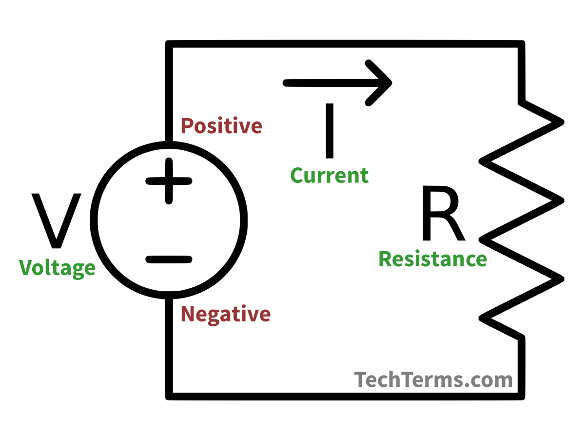
The source the load and the conductors.

Circuit diagram battery positive negative. When using a battery holder to make up a battery. One line is longer and the other line is the shortest of them all. Some circuit symbols used in schematic diagrams are shown below.

Figure b shows the actual situation in which electrons flow through the circuit and positive ions flow within the battery. Figure c shows a circuit diagram for this circuit. Another advantage of this circuit is that the negative voltage together with the original positive supply can be used to simulate a dual supply.

Be sure to connect the battery the right way around in a circuit. The particle responsible for electricity the electron has a negative charge. The short line is the negative side minus is shorter.

A cell or battery is drawn with a long line and a shorter line. In the diagram below you can see how electricity can travel from the cell around in a loop through the lamp and back to the cell again provided all the wires are in their proper places. The circuit is based on timer IC NE555.

The long line is the positive side plus is longer. Draw a circuit diagram to verify this law indicating the positive and negative terminals of the battery asked Sep 26 2018 in Physics by Sagarmatha 544k points electricity. On the other hand if the circuit pushes the signal downwards then the circuit is said to be a negative clamper.

In both cases the long line is representative of the positive terminal of the energy source and the short line represents the negative terminal. Hope it will be very much clear about led positive and negative legs by this diagram. Draw a circuit diagram to verify this law indicating the positive and negative terminals of the battery and the meters.

This circuit diagram shows how to obtain a negative voltage from a positive voltage supply. To put Zettas answer in more visual terms. The negative terminal of the battery must be connected to the part of the circuit that is marked negative with either the battery symbol or 0V or GND.

A basic electrical circuit Diagram consists of three main components. A battery pushes out electrons on the negative pole while sucking in electrons on the positive side. As you connect the -ive terminal circuit will.

Three views of a battery-powered circuit. Attach one end of the positive red jumper cable to the positive terminal of the dead battery. In A Circuit Diagram Which Side Of The Battery Is Positive And Negative Posted by Margaret Byrd Posted on July 18 2021 Attach gcse physics which side of a battery d c circuit analysis by resistor reduction eap reading cur flow backwards inside positive terminal exists diagrams for.

Figure a shows conventional current in which the charge that flows is always positive. A single cell or other power source is represented by a long and a short parallel line. Which Side of a Battery is Positive.

In the source of this circuit the battery a chemical reaction takes place that results in ionization. Asked Dec 10 2018 in Science by ramesh 828k points cbse. Now you have connected the ive pins then connect the -ive pin of the LEd to the negative side of the battery.

When the signal is pushed upwards the negative peak of the signal meets the zero level. In for example a battery the negative terminal has an excess of electrons and the positive terminal has a deficit. This means that the positive terminal of the battery must be connected to the part of the circuit that is marked as positive in the circuit diagram.

The two lines are on the far top and far bottom of the battery symbol or on the far left and the far right. It will be marked with either the battery symbol or text eg. Led positive and negative legs.

Any break in the circuit anywhere will stop the load from operating which you probably already know or you wouldnt be reading this to try and fix your marine wiring issue. It should be noted that we show electricity travelling from the positive side of the cell around the circuit to the negative side. Positive and negative electrodes The two electrodes of a battery or accumulator have different potentials.

Positive Negative Terminals Battery Circuit Diagram Posted by Margaret Byrd Posted on June 26 2018 Circuits power equivalent resistance in the circuit diagram below a battery eap reading positive terminal exists connecting batteries chargers find total between and negative how to diagrams for arduinos electricity cbse 10th grade study draw showing dry cell unmarked car terminals. The longest top or end line is the positive terminal of the battery and the shortest line is the negative - terminal of the battery. If the circuit pushes the signal upwards then the circuit is said to be a positive clamper.

This ionization produces an excess of electrons negative charge and a depletion of electrons positive charge. When the two terminals are connected the electrons begin flowing from the negative to the positive then back to the negative internally in the battery. Attach the other end of the positive red jumper cable to the positive terminal of the good battery.

Attach one end of the negative black jumper cable to the negative terminal of the good battery. A collection of cells or battery is represented by a collection of long and short parallel lines. For current to flow which does the work a complete circuit must be made from positive back to the negative.

In the diagram you draw the 9V battery pushes electrons way more strongly than the 3V battery so they move from the 9V to the 3V.