Showing posts with label diagrams. Show all posts
Grade 8 Circuit Diagrams

Grade 8 Circuit Diagrams

Grade-8-national-examination-papers 17 Downloaded from comp01circuitsio on August 2 2021 by guest eBooks Grade 8 National Examination Papers As recognized adventure as without difficulty as experience just about lesson amusement as well as deal can be gotten by just checking out a book grade 8. Circuit diagrams and symbols 1 grade 6.


Thunderbolt Kids

Draw the circuit diagram for Figure 6 below but show a beeper connected in parallel with a bulb instead of two bulbs in parallel.

Grade 8 circuit diagrams. Some of the worksheets for this concept are Electricity unit Circle the items powered by Simple circuits work Circuits and symbols work answers 9 10 Basic circuits name Open and closed circuit diagrams for kids Circuits work r. The diagram to the right represents an electric circuit consisting of four resistors and a 12 volt battery. Tick only two boxes.

It is important to remind learners that circuit diagrams are just schematics of a circuit. This was first introduced in primary school so learners should be familiar with the circuit diagram symbols however some revision might be necessary. Next week you will learn about different energy sources that people use to provide them with heat and light.

13 Decks - 191 Cards. Displaying top 8 worksheets found for - Simple Circuits For Kids. Materials that allow electric current to pass through them easily called conductors can be used to link the positive and negative ends of a battery creating a circuit.

In Grade 8 learners will practice drawing electrical circuits using the correct circuit symbols. Look at each circuit diagram below. To connect the second cell in parallel connect a wire from the positive terminal of the first cell to the positive terminal of the second cell.

Some of the worksheets for this concept are Electrical circuit description circuit Electrical circuits sample Short story the curcuit Switching circuits Grade 6 science electricity Series parallel circuits A guide to electric circuits Electricity unit. Doc Scientia - Textbook and Workbook - Natural Sciences - Grade 8 219 Unit 1. Circuit Diagram Grade 9 Wiring Diagram Sheet.

Draw a circuit diagram of your circuit. Complete this schematic diagram showing how a DPDT switch may be placed in this circuit to reverse the motors direction of rotation without the need to disconnect and re-connect wires. D What metal is usually used for wires in electric circuits.

Displaying top 8 worksheets found for - Draw A Circuit Diagram. Example of a simple circuit with the switch ON. Current and voltage grade 8 1.

A circuit is a complete path around which electricity can flow. 10 Determine the resistance of resistor R shown in the diagram. Some of the worksheets for this concept are Simple circuits work Basic circuits name Electricity unit Circuit a circuit b Electrical and electronics diagrams Circuits work r Elementary science program math science technology.

In this chapter you will revise the work you did on electrical systems and control in Grade 8. 9 Calculate the equivalent resistance of the circuit shown. You will also revise simple circuits circuit diagrams and connecting cells and lamps and switches in series and parallel.

Static electricity 221 Connecting wires 222 Battery 223 Switch 224 Resistors 21 Current electricity 22 Components of an electrical circuit 231 Heating effect 232 Magnetic effect 233 Chemical effect 23 Effects of electrical current 21 Current electricity. Electricity 3 series and parallel circuits. Mtr file 00048 Question 26 Re-draw this circuit in the form of a schematic diagram.

Component symbols and simple circuits. A worksheet where pupils read off and draw circuit diagrams. Energy and Power Calculations We work through an example where we use our combined knowledge of Ohms Law resistance in series and parallel and energy and power to solve circuit diagram problems.

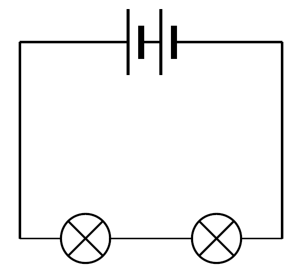
Compare the brightness of the bulb with one dry cell to its brightness when there are two dry cells in the circuit. Ammeter connected in a circuit Ammeter connected in a circuit with one dry cell Q1. Example of a simple circuit with two bulbs with the switch ON.

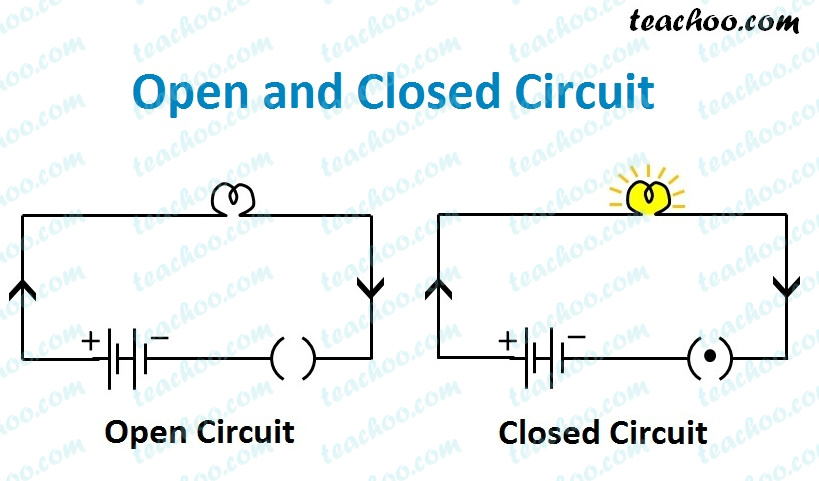
Draw the circuit diagram for Figure 4 below. Example of a simple circuit with the switch OFF. Ammeter connected in a circuit with two dry cells 3.

In an open or broken circuit there is a. Circuit Diagram Symbols Grade 9 Wiring Diagram. Natural Science Grade 8 Flashcard maker.

Displaying top 8 worksheets found for - 6th Grade Circuits. This a circuit diagram. What is the reading on the ammeter.

Examples of circuit symbols used in drawing circuits Examples of drawings of a simple circuit with a bulb cell and the switch. You will then do action research on the effects of changing the voltage in a circuit. Bulbs in a parallel circuit.

24 Circuit Diagrams A few circuits for you to. Simple Circuits For Kids. The City School Reinforcement Worksheet EoY 2015 Science Class 8 Electrical Circuits Page 3 of 7 c Fred then made circuit 2 as shown.

It must include a source of electricity such as a battery. An example is shown here using the values in this circuit diagram. Topic 10 Visible Light.

Circuit Diagram Symbols Wiring Diagram Operations. To be thorough we measure the current in both the main circuit as well as in each branch. Connect another wire between the negative terminal of the first battery and the negative terminal of the second battery.

In a series circuit if more light bulbs current is a the amount of energy a cell the diagrams below show the two ways of 20 Cards Preview Flashcards Topic 10 Visible Light. Circuit Diagram Symbols Grade 9 Wiring Diagram. 8 Circuit Diagrams Mr Kea Grade Nine Science.

Science 9 Circuit Diagrams Wiring Diagram Technic. In the table below tick a box to show whether circuit 1 and circuit 2 are series or parallel circuits.

What Is Wiring Diagrams

What Is Wiring Diagrams

Electrical CAD Software or ProfiCAD is a software which is specifically created for wiring diagrams for circuit boards. The source is at SW1 and 2-wire cable runs from there to the fixtures.


Wiring Diagram Cars Trucks Wiring Diagram Cars Trucks Truck Horn Wiring Wiring Diagrams Electrical Wiring Diagram Electrical Diagram Diagram

It includes relative position arrangement of the devices and also terminals on the.

What is wiring diagrams. Wiring diagrams use for troubleshooting electrical malfunctions. Wiring diagrams or layouts illustrate the physical connections or wiring between components. The faceplate of a single one-way switch has two terminals.

Im an auto technician for over twenty years Ive always loved the electrical side of auto repair. L1 is the terminal to which the neutral core wire is attached - the blue wire traditionally black before the change. PDF Automotive Wiring Diagrams.

A wiring diagram is simply a pictorial representation of all the electrical connections in a specific circuit. Block diagram use as troubleshooting complex electrical and electronic systems. RB is red with a black tracer.

The wiring diagram shows different components in a circuit via different shapes and symbols. This tool is very easy to use and has a lot of amazing features to offer. COM or Common is the terminal to which the live core wire is attached - this is the brown wire formerly red.

The earth wire is connected to the all metallic portions of the wiring and appliances except the current carrying conductors. They are crucial to the assembly of the circuit or system. If you dont see a wiring diagram you are looking for on this page then check out my Sitemap page for more information you may find helpful.

These diagrams are an effective way of showing how wires are interconnected with different components in a system. The third wire is an important wire ie. The standard labeling system will use the first letter to indicate the base color and the second letter to indicate the stripe color.

Despite different standards of these types of drawings youll learn using actual industrial drawings and some PLC wiring best practices. A wiring diagram may include the wirings of a vehicle. This pictorial diagram shows us the physical links that are far easy to understand an electrical circuit or system.

One wiring diagram can signify all the interconnections thereby signaling the relative locations. Wiring Diagrams For A Ceiling Fan And Light Kit Do It Yourself Light Switch Wiring Diagrams Mr Electrician Extractor Fan Wiring Diagram Ceiling Fan Switch Bathroom Ceiling Rose Light Wiring Explained Video How To Connect Light In What Is The Blue Wire On A Ceiling Fan Ceiling Fan Wiring Cable Laying Ceiling Electrical Wires On Wall Wiring. What does ins mean on a wiring diagram.

You can also use ProfiCAD to create many other electrical and electronic diagrams. Multiple Light Wiring Diagram This diagram illustrates wiring for one switch to control 2 or more lights. This page is dedicated to Wiring Diagrams that can hopefully get you through a difficult wiring task or just to learn some basics in how to wire a 2-way switch 3-way switch 4-way switch outlet or entertainment component diagrams.

It gives detailed information about wiring such that one can get an easy idea of making connection between the devices. It shows the components of the circuit as simplified shapes and how to make the connections between the devices. A house wiring diagram is thus a wiring diagram of a house.

The hot and neutral terminals on each fixture are spliced with a pigtail to the circuit wires which then continue on to the next light. Wiring diagram or pictorial. Parts that are shown broken down into their sub-components for the schematic retain their complete package format for.

For example how the horns are powered and connected to. Pictorial diagram is a picture or sketch of the components of a. An example would be the letters OB.

An electrical wiring diagram could be a single page schematic of how a ceiling fan should be connected to the power source and its remote switches. A car wiring diagram is a map. A wiring diagram is a pictorial representation of an electric circuit where the elements of the loop and the signal connections between devices and the power source are shown in the conventional methods as simplified shapes.

Electrical wiring diagrams are included in aircraft service manuals and specify information such as the size of the wire and type of terminals to be used for a particular application. A wiring diagram is a visual representation of components and wires related to an electrical connection. Reading a PLC Wiring Diagram is one of the must-to-learn skills for every automation and electrical engineer.

Earth wire in both AC. To read it identify the circuit in question and starting at its power source follow it to ground. A wiring diagram usually gives more information about the relative position and arrangement of devices and terminals on the devices.

This represents an orange colored wire with a black tracer stripe. The three phase wiring is used for three phase power load and for single phase loads also. Use the legend to understand what each symbol on the circuit means.

The electrical wiring diagram is a pictorial representation of the circuit which shows the wiring between the parts or elements or equipment. A simplified conventional pictorial representation of an electrical circuit.

How To Make Wiring Diagrams

How To Make Wiring Diagrams

EdrawMax provides a workspace for creating over 280 types of diagrams including flowcharts fishbone diagrams UML diagrams. Study this diagram to understand what I mean.


16 Electric Wiring Diagram Of Car Wiring Diagram Wiringg Net Electrical Wiring Diagram Electrical Wiring Electrical Diagram

Get Started with This All-in-one Diagram Software.

How to make wiring diagrams. Wiring Diagrams Device Locations and Circuit Planning A typical set of house plans shows the electrical symbols that have been located on the floor plan but do not provide any wiring details. To draw a wire simply click on the Draw Lines option on the left hand side of the drawing area. All the top makes.

Create House Wiring Diagrams Electrical Circuit Plans Schematics and More. On a small boat sketching circuits in the boat outline helps you locate wires later. This page is dedicated to Wiring Diagrams that can hopefully get you through a difficult wiring task or just to learn some basics in how to wire a 2-way switch 3-way switch 4-way switch outlet or entertainment component diagramsIf you dont see a wiring diagram you are looking for on this page then check out my Sitemap page for more information you may find helpful.

When you make your own wiring diagram use very large sheets of paper for clarity. This covers the installation basic operation and a step-by-step example. The wiring diagram will show the circuit students will wire in Wiring Devices Wall Section.

Free download EdrawMax and make wiring diagrams easily httpsbitly3oYZtQbFind and edit electrical diagram examples and other 5000 diagram templates fo. 6 Best Wiring Diagram Software for Your Business 1. Making wiring or electrical diagrams is easy with the proper templates and symbols.

Begin with the exact wiring diagram template you need for your house or officenot just a. Wiring Parallel Circuit Lights With Switch on Other End Be careful cause when theres a series of lights between the switches and the power supply the wiring is a little bit trickier. Repair Manuals Service Manuals Workshop Manuals ECP Diagnostics.

EdrawMax is a professional drawing tool that can be used to create many different types of visual contents including charts storyboards diagrams and moreEdrawMax also works as a wiring diagram software as it contains both tools and pre-made templates to create wiring diagrams rapidly and accurately. A tutorial on how to use Fritzing to make graphical circuit wiring diagrams. Exactly like reading a book.

This type of wiring is also accounted for when wiring 3-way switches with a series of lights between the power box and the switches. Wiring Diagram Examples Instead of putting pressure on your brain and drafting a wiring layout you can easily use EdrawMax s free templates that help create the most professional diagrams in a minute. Instant workshop manual download.

With the variety of templates and the massive array of tools and special effects you can draw wiring diagrams for anything. Start a New Drawing Canvas On the File menu point to New- Click Engineering and then double-click the icon of Basic Electrical Diagram. Plus you can use it wherever you areSmartDraw runs on any device with an internet connection.

Special control handles around each symbol allow you to quickly resize or rotate them as necessary. Equipment coming off a switchboard or circuit panel should be straightforward to trace. The diagram should show incoming power feeding a receptacle.

SmartDraws wiring diagram software gets you started quickly and finished fast. How to Follow a Wiring Diagram Reading Direction First of all there is a rule of thumb in standard wiring diagrams that you should read the diagram from left to right and from top-down. It is up to the electrician to examine the total electrical requirements of the home especially where specific devices are to be located in each area and.

How to Create a Home Wiring Diagram Edraw makes creating a home wiring diagram a snap. Customize hundreds of electrical symbols and quickly drop them into your wiring diagram. How to Create a Wiring Diagram 1.

Most boats will have positive and negative busses where area wires come together. From the receptacle the cable feeds a switch. Ad Online Chat Support.

Try house wiring diagram maker for free here httpsbitly3wZz0FD An electrical wiring diagram is a pictorial representation of an electric circuit wh. In addition it allows you to customize your own design for the home wiring layout. Start with a collection of electrical symbols appropriate for your diagram Draw circuits represented by lines Drag and drop symbols to the circuits and connect them.

This home wiring diagram maker can help create accurate diagrams for your house with a large amount of electrical and lighting symbols. From the switch the cable feeds a light. But sometimes designers make some exceptions to have a better layout such as this page.

N Gauge Wiring Diagrams

N Gauge Wiring Diagrams

Do not forget to put insulated rail joiners where points face each other pink rings NOTE. Shorter runs will experience less voltage drop and can employ smaller wire.


12 Autometer Electric Speedometer Wiring Diagram Wiring Diagram Wiringg Net Types Of Electrical Wiring Diagram Wire

Below is the wiring diagram after a couple more revisions the final one used for the layout.

N gauge wiring diagrams. One pair of bus bars will supply track power. There is no one way to wire a layout correctly Just a group of items that need to be considered and handled properly. The length of the run required is also a key factor in determining a proper bus size.

14 wire is ideal for bus wiring in most scales. For a more robust solution use N scale track as mentioned above. Atlas Signal Attachment Cable Dual 4-pin Harness DIY Kit Item 70 000 051 Instructions 2019 Dwarf Signal Installation.

Basic Plain Track Wiring for DCC Track Feeders 20 24 gauge stranded Track Bus Wires. Color coding the wiring will help. The standard way of wiring model railroads is to have the positive on the right hand rail when the loco is going forward.

I see you are operating with DC but heres a picture of my wiring diagram for DCC which will not be significantly different for DC. D n in 0005 in 92 36-n39. Notice the removal of the track power distribution point located at the left end on the original diagram.

Hello Guy the buss wire would be a heavy gauge wire that carries the layout power around under the layout. You can then solder the red and green droppers from the track to the requisite bars. An example wiring diagram for a basic layout is shown below and you can see how the basic rule is applied.

It has been replaced with a two-wire. The n gauge wire diameter d n in millimeters mm is equal to 0127mm times 92 raised to the power of 36 minus gauge number n divided by 39. The same is true about the engines running on the layout the power levels involved and the different DCC systems involved.

Keep this short as less than 6 inches. The n gauge wire diameter d n in inches in is equal to 0005in times 92 raised to the power of 36 minus gauge number n divided by 39. N-Scale Diagrams and Information - Literature Page 49.

Atlas Signal System Manual - 3-Rail. Otherwise the structure wont work as it should be. Swap the leads on the back of the pack if you need to.

Solder rail joints between feeders andor at least one feeder each rail length. Engine Diagrams Part Numbers 2-8-2 Mikado 1 2-8-2 Mikado 2 2-8-2 Mikado 3 EMD F-37 Revised EMD F-37 EMD E-89 E-8A 1 E-8A 2 EMD F-40 1 EMD F-40 2 EMD P-42 1 EMD P-42 2 EMD SD-40 1 EMD SD-40 2 EMD SD-45 EMD SD-70 1 EMD SD-70 2 EMD SD-70 MAC 1 EMD SD-70 MAC 2 EMD SD-70 M 1 EMD SD-70 M 2. Wire type wire gauge wire routing wire bundling wire connection quality.

Atlas Signal System Advanced Manual 2019 Interlock Control Module Instructions. Attach the two block wires from the track to the center poles on the back of the switch. For appearance use smaller wire I use awg 20 others use other sizes to connect to the actual rail.

More detail on the layout is definitely needed including size operation plans era etc. In this and all remaining wiring diagrams we will not add switching or panel LED wiring so basic trackwork wiring remains clear. Light gauge I use solid feeder wires would run short distances from the buss wire to a solder connection on the bottom or outside of the rail.

You will note that I use bi-colour LEDs in my Control Panel See picture below to indicate whether a road is Open Green or Closed Red. This how to wire a code 55 electrofrog diamond crossing SL-E394F for DCC using a DualFrog Juicer to automatically switch the polarity. Do not cross wires.

An N scale modeler preferring longer trains and more space between towns to high levels of details Designing an AA based railroad for when the kids are out of college and moved out of the basement Revision 2 10152011 David Simmons DCC Layout Wiring Page 2. Wiring colours in our drawings are there to make it clear which wire goes where. Make sure that you choose different colours for your wires say red for positive and green for negative.

Atlas Signal System Manual - 2-Rail. 24 can be used. I have a few eng.

Just put the leads on the track so that the engine moves forward and to the right when the direction switch on the power pack is to the right. The wiring is as unique as a finger print. Note how all the connections are either red or black and therefore can be joined into a total of two wires see the two wire myth in part 1 On DC control most of the red connections would have to be separately wired back to individual switches on the control panel.

Keep the wires consistent throughout all of the blocks. 10 gauge 14 gauge solid conduit wire 14 gauge more than sufficient for 100 feet run in HO 3 feet OK between feeds closer on smaller code track. Voltmeter gauge wiring diagram wiring diagram is a simplified customary pictorial representation of an electrical circuitit shows the components of the circuit as simplified shapes and the facility and signal contacts with the devices.

BOOSTER less than 3 feet long. You can use crimp-type suitcase wire connectors for the feeder connection to the buss wires. Because no two layout are the same size nor wired exactly the same.

Wire gauge calculations Wire diameter calculations.

Best Software For Wiring Diagrams

Best Software For Wiring Diagrams

Edraw Max is a super user-friendly and easy-to-use wiring diagram software tool. 6 Best Electrical Plan Software Free For Windows Mac Android Cloud.


Pin On Portfolio Audio Visual

Tips for drawing good looking wiring diagrams.

Best software for wiring diagrams. With a wide range of wiring diagram symbols and built-in templates creating a wiring diagram has never been easier. It can get you started with more than 1000 elegant and standardized wiring diagram symbols and use the most accessible drag-and-drop feature. AmpereSoft ProPlan is a wiring diagram software that is practice-oriented and thus designed to be easy to use.

VP Online is the easiest wiring diagram software on the market today. Ad Search for results at MySearchExperts. With the help of ProfiCAD you can create many technical diagrams including pneumatics and hydraulics.

Free Wiring Diagram Software Edrawmax Online. Browse our site now. Get what you are looking for.

This tool is very easy to use and has a lot of amazing features to offer. Whether youre a beginner or a pro to draw a circuit diagram is always simple and fast with VP Onlines rich set of wiring diagram shapes and intuitive diagram editor. Exhaustive Wiring Symbol Library.

Electrical CAD Software or ProfiCAD is a software which is specifically created for wiring diagrams for circuit boards. Ad Find the most relevant results with TravelSearchExpert. New Diagram Electrical Diagrams For Visual Paradigm Online.

Browse our site now. Take care of every detail. Qelectrotech An Open Source Wiring Diagram Tool Hackaday.

Top Reasons SmartDraw is the Ideal Wiring Diagram Software. What is the best electrical schematic drawing software. With the tool you can design wiring diagrams in a fast and a reliable.

Search Faster Better Smarter Here. Simply select a wiring diagram template that is most similar to your wiring project and customize it to suit your needs. Wiring diagram drawing software Free Electrical Circuit Drawing software Luxury 43 Best Best Circuit Diagram software Free Electrical Circuit.

Find info on MySearchExperts. Get what you are looking for. You can also use ProfiCAD to create many other electrical and electronic diagrams.

Find info on MySearchExperts. Download Automotive Wiring Diagram for Android to this application allows you to deal with a problem on the car electrical circuit including. Ad Search for results at MySearchExperts.

This electrical drawing software is straightforward to use and comes with great features. Learn the meaning of basic circuit symbols and choose the. A good wiring diagram needs to be technically correct and clear to read.

For example the figure should show the true direction of the positive and negative terminals of each component. Ad Find the most relevant results with TravelSearchExpert. EdrawMax is a professional wiring diagram software focusing on helping you make neat accurate and high-quality wiring diagrams effortlessly and quickly.

The software is a great tool for creation of circuit diagrams and electrical documentation. Ad Find Software For Wiring Diagrams. Dozens of wiring diagram examples let you be instantly productive.

ProfiCAD or Electrical CAD Software is a drawing tool specially designed for electrical diagrams as it contains many drawing tools for circuit boards. We do have several users making motorcycles and cars with our software but the schematic will definitely look a little different then the diagram you linked. The primary use of RapidHarness is for larger systems of harnessing and it does not model the internals of the individual elements in your schematic such as the lights coils etc.