Showing posts sorted by date for query simple car sound system diagram. Sort by relevance Show all posts
Best Konzert 502 Amplifier Circuit Diagram References

Best Konzert 502 Amplifier Circuit Diagram References


Best Konzert 502 Amplifier Circuit Diagram References. A can be really a visual presentation of an electrical circuit with plain graphics of elements or business standard. Web 27 rows electronics service manual exchange :.

Konzert Amplifier 502 Schematic Diagram Volume Control For Konzert
Konzert Amplifier 502 Schematic Diagram Volume Control For Konzert from oc-diy.blogspot.com

Troubleshoot konzert av 502a original totally no sound youtube. Web volume control for konzert amplifier av502b amplifier 100k shopee philippines schema sony amplifier schematic diagram full hd dealii kinggo fr. This is linear power amplifier 2000 watt which need advance knowledge in electronics since the schematic diagram is very complex for hand made.

Incredible Car Amplifier Wiring Diagram Installation Ideas

Incredible Car Amplifier Wiring Diagram Installation Ideas


Incredible Car Amplifier Wiring Diagram Installation Ideas. Web car amplifier wiring diagram installation. Web the car stereo wiring diagram makes it very simple to installation a touch screen car stereo.

Amp Wiring Diagram Car Amplifier Wiring Diagrams How To Add An
Amp Wiring Diagram Car Amplifier Wiring Diagrams How To Add An from antoinettelynnes.blogspot.com

Web you will need to remove a small portion of the speaker wire from your stereo and the amp speaker wire. Amp wiring diagram | fuse box and wiring diagram stickerdeals.net. Web car anatomy and repair, electric car, engine, how a car works, construction.

P A Amplifier Circuit Diagram

P A Amplifier Circuit Diagram

PA System Schematic Diagram. The standard power version uses one transistor Q4 and the high power version uses two.


Schematic Diagram B500 Apex 500w Power Amplifier Power Amplifiers Electronics Circuit Amplifier

And the output circuit collector - base is reverse biased having high voltage V CC.

P a amplifier circuit diagram. The transistor behaves as an amplifier when the input circuit emitter - base is forward biased having low voltage V BB. I recommend this circuit Because sound is very loud. The Pre-Amp supply was pulsing so I re-soldered every component in it up to the 18V supply.

Purple sparks of 8 mm length were observed within the valve and across the output transformer terminals. The conclusion is - clean up the solder joint and component pins. Self-oscillation of the PA produced some colourful displays due to high voltage flash-over.

Generally the Sound Amplifier system uses below topology shown in the block diagram. The transistor acts as an amplifier when the emitter-base junction is forward biased and the collector-emitter junction is reverse biased with a high voltage V CC. Please use a good quality one battery for this amplifier.

CARLSBRO 50 TOP AMPLIFIER. The circuit diagram of an n-p-n transistor amplifier in CE configuration is given. This is the diagram of this simple amplifier.

The illustration below shows how the principal components common to most PA systems connect to each other. I un-soldered the ten pins on each TA7205AP amplifier lightly sanded the pins fluxed and resolders. 2 Circuit Description The following descriptions should be read as an aid to understanding the block and schematic diagrams at the rear of this manual.

Its a simple easy amplifier circuit diagram using 2N3055 only. 100 120 Watts Amplifier circuit. Low-level signals from instrument pickups and microphones are routed to the mixers.

If you are looking for a 100-watt OTL amplifier circuit For the job a small PA system The news spread in the village or the sound system for the conference. If we are beginner then this post for us. When compared to other circuits at power are equal and very durable.

It also jerked every now and again. Amplifier Circuit using a single 2N3055 The circuit is the most basic form of power amplifier which can be build using a single 2N3055 BJT. As you can see in the above block diagram Power Amplifier is the last stage which is directly connected to the load.

P-A250 Diagram compliance is met when products are used in accordance with the relevant user guide. Each schematic is individually digitized in high resolution to provide the clearest possible scan in a downloadable printable Adobe PDF file. Generally before Power Amplifier the signal is corrected using Pre Amplifiers and Voltage controls amplifiers.

Public Address PA amplifier and tube audio schematics and diagrams for the manufacturers and brands listed below are published service data from vintage sources. The circuit diagram for n-p-n transistor in CE configuration is as shown below. Peavey roadmaster amp circuit diagram 283 KB peavey rockmaster 91 schematic 409 KB peavey rockmaster preamp 1 MB peavey semiconductor cross reference list 117 KB peavey series400 1 MB peavey series a 278 KB peavey solo 56 KB peavey solo schematic 56 KB peavey standard pa 181 KB peavey standard pa schematic 88 KB.

We can use 12 voltage to 24 voltage. P-A250 250W Class-D Amplifier Module If ordering as a replacement part specify part K-P-A250. With special thanksto my friend Peter from Carlsbro for helping make these schematicsavailable to the World.

Initial tests Initial tests with the amplifier were very exciting. Most of these early tube amplifier. In the interests of product improvement we reserve the right to change specification or design without prior notice.

21 Amplifiers The RF power amplification is provided by one or two transistors Q4 and Q5. 2 Connect a DMM set at current range in series with the positive of the power supply to the circuit 3 Next adjust the preset such that the meter reads an input of 50mA thats all the amplifiers quiescent current is set and now the connections may be restored for. CARLSBRO 50 TOP 2 AMPLIFIER.

There was some sound but not a lot. 85 rows 50W audio power amplifier circuit diagram. The arrows show the direction of signal flow.

Although the amplifier above looks too simple to make the low-tech design forces the 2N3055 to dissipate a lot power through heat. All PA Systems - from the smallest to the largest - follow the same basic format. We can use this type of amplifier for our car.

CARLSBRO CS4050 TOP AMPLIFIER. Both internal and external to the valve envelope.

Wiring Diagram 5 Channel Amp

Wiring Diagram 5 Channel Amp

Then cut a length of ground wire with 18 inches or even less. 3 A better suggestion from an expert like you.


Component Car Stereo Wiring Diagram Google Search Car Audio Systems Speakers Car Audio Car Audio Systems

Doubling the number of speakers or amount of power does not double the volume.

Wiring diagram 5 channel amp. 5 Channel Amp Wiring Diagram wiring diagram is a simplified tolerable pictorial representation of an electrical circuit. The bare metal until it is shiny and clean sand the paint at the said spot. The system depicted includes new speakers an aftermarket receiver a 4 channel amp for the front and rear pairs of full range speakers and a mono amp for a subwoofer.

People now are. 5 Channel Amp Wiring Diagram Source. Amp for front channel use.

Therefore if you have a home stereo or car stereo in which 2-way speakers are used youll have to add more 2-way speakers if the total impedance can be supported by the amplifier or add more amplifier channels for more sound. There are two things that will be present in almost any Rockford Fosgate Amp Wiring Diagram. Each component ought to be placed and connected with different parts in specific way.

Amplifier wiring diagrams how to add wire 5 channel amp simple step 4 speakers and a sub 2007 2020 toyota tundra plug n play help needed asap polaris diagram 2 full digital mosfet front rear high level input page car application audiocontrol 6 s2ki connect new boss gt980 1200w pros bridge an 7 steps in your four 5th audio stereo forum low pass filter hpf crossover fusion signature systems install two amps. A 5 channel amp is considered as the ideal choice. Here is a picture gallery about 5 channel amp wiring diagram complete with the description of the image please find the image you need.

We can find the power using this formula. 5 Channel Amp Wiring Diagram Fresh Contemporary How to Wire A Subwoofer In A Car Gift 5 channel amplifier wiring diagram 5 channel amplifier wiring diagram as well as 1kva 1000 watts pure sine wave inverter along with symbol also 4 channel marine power lifierpublic address. 2 Run a well-powered 5-channel amp with the 35 and 6x9s in parallel from channels 1-2 the rear 525 from channels 3-4 and the sub from channel 5.

Attach the power cable to the positive battery terminal not directly to the battery post itself. 5 Channel Amp Wiring Diagram Fresh Contemporary How to Wire A Subwoofer In A Car Gift 5 channel amplifier wiring diagram 5 channel amplifier wiring diagram as well as 1kva 1000 watts pure sine wave inverter along with symbol also 4 channel marine power lifierpublic address. 5 Channel Amphigh Level Input Page 2 Ford F150 Forum for 5 Channel Amp Wiring Diagram image size 700 X 604 px image source.

Here is a picture gallery about how to wire a 5 channel amp diagram complete with the description of the image please find the image you need. Another thing you will get a circuit diagram could be lines. 1 Run the dash 35 and rear 525 from the head unit and run the door 6x9s and sub off of a 3-channel amp.

You will need to use the high-level input wires at right. 5 channel amp wiring diagrams. Connect these RCA low level plugs coming from radio to these inputs of the amplifier.

Read the particular schematic like the roadmap. And for ground wiring you have to look for a section of sheet metal within 18 inches of the mounting location of your 5 channel amp. 5 Channel Amp Wiring Diagram Source.

2 Channel amplifier audio input wiring. Read typically the schematic like the roadmap. Connecting Your Car Speakers To An Amp.

Amplifier Wiring Diagram pertaining to How To Wire A 5 Channel Amp Diagram image size 612 X 792 px. 5 channel car amplifier wiring diagram Indeed recently has been sought by consumers around us perhaps one of you. The first component is symbol that indicate electrical element in the circuit.

Step 5 Connect the power wire. In this video we show you how we prep a 5 channel amp before we install it into a carthe amp use in this video is the Kenwood x801-5 our unboxing video can. Ch2 or Channel 2 right If your radio does not have RCA plugs out.

Wiring Diagram 5 Channel 13 Kicker Wiring Diagram Detailed 5 Channel Amp Wiring Diagram Wiring Diagram includes many detailed illustrations that present the connection of assorted things. A circuit is generally composed by several components. Use Your Factory Wiring inside How To Wire A 5 Channel Amp Diagram image size 500 X 330 px.

It includes instructions and diagrams for different varieties of wiring techniques as well as other items like lights home windows etc. I see three options. Ch1 or channel 1 left.

If you like the picture on our website please do not hesitate to visit again and get inspiration from our website. It shows the components of the circuit as simplified shapes and the capacity and signal contacts amongst the devices. Check out our amplifier wiring diagram to see how the wiring gets connected in a typical 2-amp system.

Schematic Diagram Bulb

Schematic Diagram Bulb

The inside of a light bulb showing Tungsten and lead wire along with standard dimensions according to. Write your ideas in the callout with exquisite clipart.


How To Wire Switches In Parallel Controlling Light From Parlallel Switching Wire Switch Switches Home Electrical Wiring

Power Amplifier Circuit 25 Watts Schematic Circuit Diagram.

Schematic diagram bulb. Cfl Bulb Schematic Diagram Compact Fluorescent Lamp CFL pavouk org. Posted by Margaret Byrd Posted on October 17 2017. Early people used candles and oil lamps for light.

Heres a bulb diagram that perfectly fits brainstorming in business. Parallel Circuits Schematic Diagrams Part 2. Amazon com fluorescent lamps wiring diagrams.

Schematic Diagram Business Information Business analysis business Logo explanation business Meeting Flowchart Step light Bulb arrows clipart Download clipart 13001520px 72dpi Image uploaded by our users. Parallel circuits schematic diagrams 12w led light bulb incandescent lamps bulbs 1 teardown a19 edn my circuitlab how electrical work lighting 应用方案 英文 uvc fluorescent circuit installed series 5 5w. 19 Watts Simple Amplifier Schematic Circuit Diagram.

Incandescent Bulb schematic. Bulb Schematic Diagram. Schematic of the sound activated lights circuit.

Here is a picture gallery about light bulb socket wiring diagram complete with the description of the image please find the image you need. In order to learn how to read a circuit diagram it is necessary to learn what the schematic symbol of a component looks like. Color temperature and brightness now go hand in hand automatically changing at.

This circuit represents a somewhat unusual blinker indicator for use in a car or model. Use a red pencil or pen to trace the flow of electricity through the bulb by using arrows on your drawings. Bulb wiring diagram easy diagrams u rh art isere com h4 headlight schematic plug wiring diagram furthermore hid controller harness on h4 rh 67 headlight bulb led h4 bulb wiring schematic schematics diagrams u rh marapolsa co h4 bulb pigtail diagram schematics wiring diagrams u rh 28 Find great deals on eBay for h4.

Click to free download them instantly. 3 Bulb Ballast Wiring Diagram wiring diagram is a simplified adequate pictorial representation of an electrical circuitIt shows the components of the circuit as simplified shapes and the faculty and signal friends amid the devices. Label the following parts of the bulb on the picture below.

2 halogen bulb with 1 switch. The IC has an integrated 500V power MOS and requires only a few peripheral components which greatly saves system cost and size. Admin May 26 2019.

Please watch this video to help you with tuning and operating your plasma ball. Mini Audio Amplifier Schematic Circuit Diagram. Schematic diagram of food warmer halogen bulb installation.

Light Bulb Socket Wiring How To Wire A Light Bulb Holder Wiring with regard to Light Bulb Socket Wiring Diagram image size 360 X 504 px and to view image details please click the image. Blinker Indicator Schematic Circuit Diagram. York Rtu Wiring Diagram.

AN1543 D Electronic Lamp Ballast Design ON Semiconductor. Low Cost 150 Watt Amplifier Schematic Circuit Diagram. How to Read Circuit Diagrams for Beginners.

Use free brainstorming templates to visualize your working and thinking processes. A three-pack of D-cells is placed in a circuit to power a flashlight bulb. Simple Circuit Diagram for Beginners Battery and Light Bulb.

Thats pretty cool if youre fond of light. Given fig shows the schematic diagram of a typical electric circuit comprising a cell an electric bulb an ammeter and a plug key clearly the electric current flows in the circuit from the certain terminal of the cell to the negative terminal of the cell through the bulb and the ammeter fig. Hi Fi Amplifier Circuit 2X12 Watts Schematic Circuit Diagram.

Gas bulb filament support wire glass bead side terminal base terminal insulator solder between side terminal and base terminal. Schematic diagram of the 12W LED light bulb The heart of the circuit is a PT4554D high precision non-isolated step-down LED constant current IC. York Simplicity VAV RTU.

Halogen Bulb Circuit Diagram Posted by Margaret Byrd Posted on November 5 2019 Halogen light switch circuit 34 tungsten lamp power supply soft start for 12 volt lamps 4 shows schematic diagram spectra electronic transformer smps components bulbs from dimmer with replace inefficient mr16 saver bikes transformers. Circuit or schematic diagrams consist of symbols representing physical components and lines representing wires or electrical conductors. It is also necessary to understand how the components are connected together in the circuit.

14 Light Bulb Schematic. Diy Rip Fence 13945744403500213888 - We did not. Compact Fluorescent Light Bulb Schematic WordPress com.

Ethernet Cross Cable Diagram - Ethernet Cross Cabl. Diy Rain Barrel Diverter Earthminded 55 Gal Blue. The running-light display progresses toward the left or the right depending on which directional signal is activated.

0 12 Less than a minute. Marine Basic 12 Volt Boat Wiring Diagram Battery. Wiring Diagrams hid venturelighting com.

Gallery Headlight Bulb Wiring Diagram Fantastic Images. 3 Way Switch Single Pole Wiring Diagram - Adding A. Use circuit symbols to construct schematic diagrams for the following circuits.

4 X 15 Watt power amplifier schematic circuit diagram. A single cell light bulb and switch are placed together in a circuit such that the switch can be opened and closed to turn the light bulb on. Cfl Circuit Cfl Circuit Suppliers and Manufacturers at.

Wiring Diagram Nc

Wiring Diagram Nc

Miata community wiki nc bosectomy mazda protege headlight wiring 126 mx 5 ls 2005 air con nb dash swap menders diagrams 1990 to mx5 2006 2018 essential owner s manual stereo diagram ecu forum car radio audio work free pdf mazdasd engine control system and repair manuals index of garage conditioning 2009 pictures 2008 factory official service heated seats page 1 seat kit city 3 2003. The new parallel breakout board appears a bit different but the process of wiring and testing is the same.


Ah3 3 On Delay Timer Electrical Circuit Diagram Timer Electrical Engineering Books

Wrg 1056 Nc700x Wiring Diagram.

Wiring diagram nc. If the relay is powered and the switch is closed COM and NO have continuity. This is the terminal where you connect the device that you want powered when the relay receives no power. The normally open auxiliary contact connected in parallel with the two start.

Fritzing Project Relay Test Circuit N O N C. The circuit is from the GND to the input Here is the diagram for the Mach3 USB board pins I1 through I4 are used for input. COM- This is the common of the relay.

No Nc Wiring Diagram wiring diagram is a simplified adequate pictorial representation of an electrical circuit. Service manual on CD for and Honda NCX NCXA NCXD and Honda NC NC. The wiring of the parallel breakout board from the output terminals to the driver digital pulse step pulse and direction lines are explained.

Color Wiring Diagrams IndexHonda Ncx Owners Manual will be a The manual also covers the NCX and has a wiring diagram for it. Nc Switch Diagram Wiring Diagram General Helper Beginning students often find the terminology for switches confusing because the words open and closed sound similar to the terminology used for doors but do not mean quite the same thing when used in reference to a switch. Need wiring diagram from mach3 USB breakout board to inverter.

Wrg 5047 Micro Switch No Nc Wiring Diagram. Vfd is a short form of variable frequency drive or variable voltage variable frequency driveThe VFDs are working based on changing the input frequency and input voltage of the motor we can change the speed of. How about a diagram to reference showing the pin-out to use Here is the diagram for the parallel breakout board pins 10 through 13 are used for input.

Wrg 1056 Starter Push On Wiring Diagram. VFD Start Stop Wiring Diagram. The device connected to NC will be on when the relay has no power and will turn off when the relay receives power.

Whether its practical DIY home-improvement tips gadgets and digital technology information on the newest cars or the latest breakthroughs in science -- PM is the ultimate guide to our high-tech lifestyle. Us 12 01 11 Off Universal Motorcycle Turn Signal Light Indicators Amber Led Lights For Honda Vfr Nc 700 750 800 1200 F Vfr750 Vfr800 Vfr1200 On. A wiring diagram is a simple visual representation of the physical connections and physical layout of an electrical system or circuit.

The wiring of the parallel breakout board from the output terminals to the driver digital pulse step pulse and direction lines are explained. Circuit Diagram Nc Wiring Diagram 500. So first identify the magnetic coil terminals where the power supply is to be applied.

NC- This is the Normally Closed Switch. MC Motor Starter Wiring Diagram With CB MC OL NO NC The symbol diagram is best but everyone cant understand it easily that why I always focus on imagediagram which easy and simple to understand and good for learning. Scanner Scantool Obdi Obdii Obd2 Automotive.

Wiring diagram a wiring diagram shows as closely as possible the actual location of all component parts of the device. Motor Wiring Diagram 3 Phase 10 Wirepdf. You can get the terminal identification or internal circuit diagram of every relay printed on their body or their user manual.

1980 honda nc50 wiring diagram moped wiki army express uk schematic 4 stroke net all the data for your motorcycle and us diagrams here s help adding turn signals to yamaha qt50 luvin other nopeds manual na50 ii rebuild tbolt usa tech database llc myrons mopeds 1977 1983 na scooter custom motorcycles 1981 wire harness ignition coil battery 81 parts grommet b main pipe d order at cmsnl wtb. Micro Switch No Nc Wiring Diagram. Operation of your CNC or automated machinery.

Now identify Normally Closed contacts terminals then Normally open contacts terminals. Open and close switch wiring diagram. I am here with giving you a VFD start stop wiring diagram for running a VFD through panel board push button and keypad of the VFD It is called HMI.

Blesiya No Nc Kunci Elektrik Piring Gagal Secure Dan Gagal Aman Pelat Strike Pintu Kunci. Motor Wiring Diagram 3 Phase 10 Wirepdf speedcontrol SC wires Q1 and Q2 to terminal 41 mod 2 link for torque seated valve 3 motor wiring 59 21. It shows the components of the circuit as simplified shapes and the capability and signal contacts between the devices.

Auxiliary contact no nc 10 01 10 01 10 01 10 01 10 01 11 11 11 11 11. The below diagram setting is base on 5mm screw pitch and excitation mode is 18 mircostepping. What does this symbol mean this wiring diagram.

Sometimes the contact point a is called no contact point and the contact point b is called nc contact point however the jis c 0301 graphical symbols for diagrams prescribes them as contact point a and contact point b respectively. NC no no ts close 9 14 e u lb n e e r g com NC NC ls 2 open without Page 826 3916848. Grbl Homing Using Nc Switches Class B Project.

Acces PDF Honeywell Fan Center Wiring Diagram Popular Mechanics inspires instructs and influences readers to help them master the modern world. 61mgs03 2012 2015 Honda Nc700x Xd Motorcycle Service Manual. For assembly and wiring diagram of the interlocked contactors refer to.

Sw Intlk No Nc Snap Mt. Go to the new parallel breakout board to get more information and the wiring diagram. But you know that this diagram designing takes bag time from the time of the symbol diagram.

Circuit Diagram Nc Wiring Diagram Table. Nc700x Fuse Box Wiring Diagram. My 37 year old 77 gs is apparently more powerful than a will give you a solution for you to Honda NCX Owners manual.

Schematic Circuit Diagram To

Schematic Circuit Diagram To

In these diagrams lines represent connecting wires while other elements like resistors lamps and switches are represented by standardized symbols called electrical schematic symbols. Design circuits online in your browser or using the desktop application.


Schematic Diagram Electricity Electrical Engineering Diagram

This is the circuit diagram of the 550va microtek digital inverter.

Schematic circuit diagram to. RELAY APPLICATION CIRCUITS. The circuit First Diagram utilizes double clock NE556 to create the sound. Circuit And Schematic Diagram Posted by Margaret Byrd Posted on July 20 2021 Electronic schematics what you need understanding technical difference between pictorial and how to read electrical is the circuit parallel circuits schematic diagrams electronics commonly diagram.

If your tv has lines across. Each electronic component has a symbol. Electronic Circuit Diagram - Schematic PCB Design Horn and Lamp Flasher Circuit for Car Reversing Gear Mode This is a basic circuit of car horn and lamp flasher that starts playing the vehicle horn at whatever point your vehicle is backward rigging.

We use 2 transistor and 2 resistors only. Microtek inverter high output problem. Circuit symbols are used in circuit schematic diagrams which show how a circuit is connected together electrically.

The schematic diagram should be a jpggifpngbmp file Schematics for electronic circuits are prepared by designers working with EDA Electronic Design Automation applications known as schematic capture tools or schematic entry tools. Download Lenovo schematic diagrams for all models. A circuit diagram could relate to a household appliance like an electric stove.

After seeing a few circuit diagrams youll quickly learn how to distinguish the different symbols. A schematic style circuit diagram is used to give a visual representation of an electrical circuit to an electrician. What is a circuit diagram.

A circuit diagram or a schematic diagram is a technical drawing of how to connect electronic components to get a certain function. Circuit diagrams tend to be more pictorial the actual layout of a terminal strip for example being depicted. With the circuit shown in Figure 17 Led1 can be switched off by relay and button control.

The blue path can not be used. Schematic diagrams are typically associated with electrical circuits. Circuit Diagram is a free application for making electronic circuit diagrams and exporting them as images.

Most of the industrial standard circuit items can be changed in the appearance style and color according to the requirement. Every symbol or sign represents various meaning about the topi. Also called wiring diagrams or circuit diagrams these diagrams show how the different components of a circuit are connected.

In a schematic circuit diagram the presentation of electrical components and wiring does not entirely correspond to the physical arrangements in the real device. Lenovo A60 schematics Lenovo A60 schematics Lenovo A350 schematics Lenovo A520 schematics Lenovo A606 Schematic Lenovo A668T schematics Lenovo A690 schematics Lenovo A789 schematics Lenovo A790E schematics Lenovo A798T schematics Lenovo A800 schematics Lenovo A820 schematics. Try findchips pro for microtek ups circuit diagram.

A schematic circuit diagram represents the electrical system in the form of a picture that shows the main features or relationships but not the details. What is Schematic Diagram. Sine wave inverter circuit diagram using microcontroller arduino and program code spwm using pure sine wave inverter circuit of spwm.

The pictorial style circuit diagram would be used for a broader less technical audience. All Nokia device maintenance diagrams for all old and new models 2021 direct links download Nokia diagrams in. Samsung crt tv circuit diagram pdf.

Browse your schematic in your local computer then click upload button. Since the normally closed contact is empty the led is off when there is no voltage at the relay coil ends. Nokia schematic circuit diagrams free download pdf Download all schematic circuit diagrams for Nokia devices in an organized way via the direct links below.

Also included are links to design engineering electronics resources. The standard circuit component symbols and circuit symbols are important for circuit schematic diagrams. Here is a hisense lcd tv circuit diagram as an example.

When troubleshooting your tv you will need to use schematics and diagrams to find the problem. There is to my ear a slight implication that the schematic relates to something more complicated more electronics oriented like a radio or a computer. Crt av out y out tv av out y out monitor out power supply circuit 140v 24v 11v 9v main sound amp.

Electronic Schematics collections of free 45000 electronic circuits schematics carefully cross-referenced into 500 categories. A resistor The symbol for a resistor. A Schematic diagram has many symbols or signs.

A Schematic Diagram Of An Electric Circuit

A Schematic Diagram Of An Electric Circuit

Electronic Circuit Breaker Circuit Diagram Working and Applications. AC device that we use in our homes generally have a limit to handle the current and voltageThese threshold voltage and current are called the device rating and are the measurements given by the manufacturers in the range of which the device will work properly.


Electric Fan Schematic Diagram Best Of Ceiling Fan Switch Stand Fan Table Fan

In a schematic circuit diagram the presentation of electrical components and wiring does not entirely correspond to the physical arrangements in the real device.

A schematic diagram of an electric circuit. Electronic Circuit Diagram - Schematic PCB Design Horn and Lamp Flasher Circuit for Car Reversing Gear Mode This is a basic circuit of car horn and lamp flasher that starts playing the vehicle horn at whatever point your vehicle is backward rigging. Figure 2 shows the symbols for such basic components as wires and Understanding and Using. Physical Circuit Corresponding Schematic Diagram Ideal Sources and Ground In electronic circuits ground is used as an electrical reference point.

See more ideas about electronic schematics circuit diagram electronics. An electronic schematic diagram presents the detailed information about the circuit each of its components and how they are wired into the circuit. Figure 1shows a simple schematic diagram of a power sup-ply.

A block diagram presents the flow or functional information about a circuit but it is not a detailed depiction of the circuit. A drawing of an electrical or electronic circuit is known as a circuit diagram but can also be called a schematic diagram or just schematic. A schematic circuit diagram represents the electrical system in the form of a picture that shows the main features or relationships but not the details.

Learning how to read and understand schematics will be easy for beginners with recognizing basic schematic symbols. Oct 19 2019 - Explore Jerry Turners board Electronics Schematic Circuit Diagrams followed by 402 people on Pinterest. Electrical schematics are the maps for designing building and troubleshooting circuits.

Building Circuits Schematics Ppt Download Draw The Schematic Diagram Of An Electric Circuit Consisting Of A Battery Of Two Cells Of 1 5v Each Brainly In Resistors In Series And Parallel Boundless Physics Circuits And Current Electricity Energy Transfer In Electrical Systems Siyavula Q1 Page 213 Draw A Schematic Diagram Of A Circuit Consisting. Here are some of the standard and basic symbols for various components for electrical schematics. On it you can see some of the conventions used.

Electronic schematics use symbols for each component found in the electrical circuit even when small. A pictorial circuit diagram uses simple images of components while a schematic diagram shows the components and interconnections of the circuit using standardized symbolic representations. Plans dont show placement or scale just work and flow.

To read it identify the circuit in question and starting at its power source follow it to ground. The circuit First Diagram utilizes double clock NE556 to create the sound. A wiring diagram is a simplified traditional photographic representation of an electric circuit.

In electrical power distribution systems ground earth is the electrical potential of the Earths conductive surface. Schematic Diagrams Schematic diagrams document the connection points and construction methods of electrical and electronic circuits. Circuit or schematic diagrams consist of symbols representing physical components and lines representing wires or electrical conductors.

From this the actual operation of a piece of electronic equipment can be determined. An electrical circuit diagram is a graphic representation of special characters and pictograms that are connected in parallel or in series. A circuit diagram electrical diagram elementary diagram electronic schematic is a graphical representation of an electrical circuit.

Schematic Circuit Diagram Of Subwoofer Amplifier

Schematic Circuit Diagram Of Subwoofer Amplifier

Subwoofer audio amplifier circuit schematic role is to amplify the sound signal sounds super bass subwoofer. Here is a circuit that uses a mosfet amplifier amplicable for subwoofer as the main booster or the basis of this boosterAmplifier.


2 1 Stereo Subwoofer Preamplifier Circuit Subwoofer Audio Amplifier Electronic Circuit Design

Project 116 Subwoofer Amp.

Schematic circuit diagram of subwoofer amplifier. Voltage 18V for NE4558 and 22V for SE4558. As very low frequencies are omnidirectional a single amplifier is necessary to drive this dedicated loudspeaker. I m yahica 12v subwoofer amplifier circuit manual tda1514 40 watt audio siwire 100w tda7293 electronics projects circuits using ic tda2030 22 car diagram booster diy pinout features and its applications tda7294.

May dont be defeated because this circuit gives the electric power about 120 W that load 2 ohm. The SESANE4558 is a pin-for-pin replacement for the. This is the circuit diagram of a fully transistorized sub woofer amplifier that can produce an output of 100WThere are seven transistors including four in the output stage.

Amplifier 2 1 With Tda7377 Electronics Projects Circuits. 100 watt sub woofer amplifier working 12v subwoofer circuit manual 100w tda7293 car scematic fusebox and booster with pcb power wiring diagram pdf schematic using simple 150 tda1562 datasheet 70w high audio tda1514 40. This circuit using ic ic based on STK.

Here is a circuit that uses a mosfet amplifier amplicable for subwoofer as the main booster or the basis of this boosterAmplifier. Must use power supply source that is appropriate to 15V and -15V that current 2Amp. We also include a suitable power supply circuit with.

30 V supply voltage that has been rectified. 100 Watt Sub Woofer Amplifier Working And Circuit Diagram. Excellent channel separation allows the use of a dual.

500w A1941 C5198 Transistor 12v High Power Amplifier Board Car Subwoofer Core The Pipe All Frequency Or Pure Low Buy Cheap In An Online Store With Delivery Price Comparison Specifications - Amazing 1000w amplifier circuit gerber file download gerber file here. Subwoofer Amplifier Circuit Diagram Using Ic Tda2030. 4558D is a dual operational amplifier.

Subwoofer Amplifier Circuit Detailed Diagrams Available. The following schematic shows the subwoofer and speaker wiring diagram for alpine mrp f250 car audio amplifier system. Sw 4064 800watt Subwoofer Amplifier Circuit Diagram Wiring.

Subwoofer booster circuitbass enhancer circuit based on the IC 4558 and TL074 or commonly known as IC op-amp its suitable to be a boosting in subwoofer system which together with some. Subwoofer amplifier schematic diagram Amplifier circuit is very suitable for use in subwoofer speaker because its strong. When seeing the circuit will think to use important equipment be.

The transistors Q1 and Q2 form the preamplifier stage. Our subwoofer wiring calculator allows you to figure out how to wire your dual 1 ohm dual 2 ohm and dual 4 ohm subwoofers in several different qualities. To use it can be used on cars that use speakers or a subwoofer system in his car.

2MHz unity-gain bandwidth. 200W Subwoofer Amplifier Circuit. Transistors Q4 to Q7 form the output stage.

Since no ICs are used the circuit is very robust and can be easily assembled. Car Subwoofer Amplifier Circuit Diagram. Tda7294 Subwoofer Amplifier Circuit Electronics Projects Circuits.

Subwoofer circuit diagram. Subwoofer booster circuit is used to enhancing or boosting or increase the subwoofer amplifier but it also can improve the quality of the bass sound on an amplifier or High Power Amplifier. Device in a single amp application.

Schematic diagram of TDA2030 subwoofer amplifier circuit. Circuit which uses MOSFET Power Amplifier is powered by the output more than 200W Speaker 8 Ohm impedance. 100w Subwoofer Amplifier Circuit Electronics Projects Circuits.

100 Watt Sub Woofer Amplifier Working And Circuit Diagram. Subwoofer C5198 A1941 Amplifier Circuit Diagram. This unit is intended to be connected to an existing car stereo amplifier adding the often required extra punch to the music by driving a subwoofer.

Circuit which uses MOSFET Power Amplifier is powered by the output more than 200W Speaker 8 Ohm impedance. 200W Subwoofer Amplifier Circuit. Are circuit scheme is divided into two sides of the low-noise filter super bass who in the wake of the second unit in the operational amplifier IC TL072 RC4558 or you can using this circuit Subwoofer Booster 4558 and hand power audio amplifier with TDA1521 IC which are configured by.

Circuit Diagram 7388

Circuit Diagram 7388

Surround sound 40 with every speaker of aroun. 51 svr besides its contribution to the ripple rejection the svr capacitor governs the turn onoff time.


Pin On Tda 7388 Amplifier Circuit Diagram

MSI MS-7388 REV 31schematic circuit diagram.

Circuit diagram 7388. First you need 7388 ic. This circuit is much more similar to the datasheet circuit but the circuit has an extra low pass filter circuit for filtering. TDA7388 IC is a class ab amplifier because of its.

Audio amplifier is like a voltage amplifierThis car subwoofer circuit set Suitable for use with a great car audio system. Par speaker 50 watts. TDA7388 у всех одинаковая схема включения AMPLIFIER Pinterest.

Editor Electronic Circuit Published Monday July 20 2020. So 12 voltage 200 watts. TDA7388 audio power amplifier 4x41W.

Soma Electronics Uncategorized October 12 2018 June 22 2019 1 Minute. Amplifier circuit using Tda2030 and Tda2050. The tda7388 is an ab class audio power amplifier packaged in flexiwatt 25 and.

This ic is 4 channel class AB amplifier. TDA7388 - 450w Audio Power Amplifier Original circuit diagram tda 7388Easy and more powerful audio amplifier. High power 200W audio amplifier.

Here in this circuit diagram can make 200 watts. You have to use 12 voltage 16ampere transformer to get 200 watts from this ic. Written By phoem Thursday January 1 1970 Add Comment.

We know that voltage x ampere watts. To boost up the power of the amplifier we need to introduce two transistors in the circuit. 41 amplifier schematic diagram.

The circuit and PCB layout were designed by Barlex Respectaizer. TDA7388 Datasheet 4 X 41W QUAD BRIDGE CAR RADIO AMPLIFIER - Shenzhenshi YONGFUKANG Technology coLTD Unisonic Technologies TDA7388A 4 x 42W quad bridge car radio. 26 rows Tda7388 circuit diagram.

This is a 41 amplifier schematic diagram this diagram we can use as a car amplifier or also we can use in the home this is home theater amplifier also. The circuit employs only a few. This project can play up to 4 X 40 watts speaker easily.

The TDA7388 is a new technology class AB Audio Power Amplifier in Flexiwatt 25 package designed for high end car radio applications. Rangkaian power ampli TDA 7388 - Кладезь секретов from zoomumelecforumru. TDA7388 audio power amplifier 164W circuit diagram.

At first we need to know what is a audio amplifier. 12V Power Amplifier Subwoofer using TDA7388 IC. Tda7388 datasheet tda7388 circuit tda7388 data sheet.

Circuit Diagrams And Pcb Layout Of Tda 7388 Amp Kladez Sekretov La4440 Ic Audio Amplifier Circuit Diagram And Pcb Layout Hi Fi 4 Channel Audio Amplifier Very Simple And Cheap 6 Https Www St Com Resource En Datasheet Tda7386 Pdf Car Audio Amplifier Circuit Diagram. Thanks to the fully complementary PNPNPN output configuration the TDA7388 allows a rail. This is TDA7388 4 Channel IC Audio Amplifier Board.

200W Hybrid Audio Amplifier Circuit. We can alter the circuit diagram then we will get up to 50 watts output. I used CD7388 IC and 0-12 transformer for this project.

Find numerous efficient amplifier ic tda7388 to perform voltage switch controlling and other electronic functions. A single TDA2030 IC can deliver up to 15 watts output. Tda7388 subwoofer circuit diagram.

Output short circuit to gnd to VS across the load Very inductive loads Overrating chip temperature with soft thermal limiter Load dump voltage Fortuitous open GND Reversed battery ESD Description The TDA7388 is an AB class audio power amplifier packaged in Flexiwatt 25 and designed for high end car radio applications. Pin connection and testapplication diagrams. Assalam-o-alaikum TDA7388 160W Hi-RES Audio Amplifier Simple circuit diagram in HindiUrdu Electrical Tech For more videos please subscribe my channelEl.

Normally this is used in the car audio player. Tda7388 subwoofer circuit diagram. 10 Tda 7388 Ic Circuit Diagram.

It give you 45 watt maximum output per channel. Amplifier Circuit Tda7388 Pcb Layout. You can configure the output with your preference in this circuit diagram I.

7388 circuits diagram - Кладезь секретов. Unisonic technologies co ltd tda7388. Pin On Tda 7388 Amplifier Circuit Diagram.

TDA7388 Car Subwoofer Amplifier Circuit Diagram Surround QUAD BRIDGE car audio amplifier. 41 amplifier schematic diagram tda7388. Home Dell Schematic Msi Schematic MSI MS-7388 REV 31schematic circuit diagram.

Elcircuit will share the scheme along with the PCB layout for the power amplifier subwoofer that operates on a single 12V DC voltage or can use a 12V DC battery. Skema Ic Tda 7388 - RANGKAIAN ELEKTRONIKA ANALOG DAN DIGITAL This project can play up to 4 x 40 watts speaker easily. 41 amplifier schematic diagram tda7388Unisonic technologies co ltd tda7388.

Circuit Diagram Reading

Circuit Diagram Reading

Below are some common illustrations of equipment located on fluids circuit diagrams followed by descriptions of the most common elements. This tutorial should turn you into a fully literate schematic reader.


Reading Schematics Electronic Circuit Projects Electronics Circuit Diy Amplifier

A drawing of an electrical or electronic circuit is known as a circuit diagram but can also be called a schematic diagram or just schematic.

Circuit diagram reading. Circuit Drawings and Wiring Diagrams Description Successfully performing electrical work requires the ability to read and interpret many different types of drawings and diagrams. How to Follow a Wiring Diagram Reading Direction First of all there is a rule of thumb in standard wiring diagrams that you should read the diagram from left to right and from top-down. Reading fluids circuit diagrams - hydraulic pneumatic symbols.

The system takes 16 bit msp430f12x processor as the data processing. Circuit or schematic diagrams consist of symbols representing physical components and lines representing wires or electrical conductors. Circuit diagram direction refers to the arrangement direction of each part of the circuit diagram from the initial input to the final output.

Symbol usage depends on the audience viewing the diagram. Understanding circuit symbols and components is another one of the basic building blocks needed to become an electrician. A schematic diagram is the road map of the circuit.

This instructable will show you exactly how to read all those confusing circuit diagrams and then how to assemble the circuits on a breadboard. Knowing how to read circuits is a very useful skill that will help you out all the time. If youre new to the subject of reading circuit diagrams also called circuit schematics then one way to start is to think of them as road maps.

Heres an introduction to circuit reading associating the com ponents with the diagram and determining how they are connected together. Just as the road map uses symbols to. Learning to read electrical schematics is like learning to read maps.

A circuit diagram is like a map that shows electricity flows. Especially if you start messing around with building little electronics projects. Then well talk about how those symbols are connected on schematics to create a model of a circuit.

In order to get from one point to another you must be able to follow the appropriate route and understand the meanings of the various symbols found along the way. But sometimes designers make some exceptions to have a better layout such as this page. How to Read Circuit Diagrams.

Circuit diagrams aka schematics are line drawings that show how a circuits components are connected together. Creating such a diagram requires a sound basic knowledge of electrical engineering. For all the electronics hobbyist wannabes this is a MUST-READ instructable.

Well also go over a few tips and tricks to watch out for. When the vehicle mainly carries out fingerprint registration deletion or emergency ignition access the password key U disk to J1 to read the password information. Later in this article series we will describe some simple hydraulic and pneumatic circuits composed of these circuit elements.

The towns and villages in the map are the electronic components themselves and the lines representing highways or. An electrical schematic is a diagram that shows how all of the wires and components in an electronic circuit are connected. These two different types of circuit diagrams are called pictorial using basic images or schematic style using industry standard symbols.

Well go over all of the fundamental schematic symbols. A circuit diagram or a schematic diagram is a technical drawing of how to connect electronic components to get a certain function. From the basiscs like the meaning of an alternating circuit to the exact workings of light switches sockets and the like.

In order to learn how to read a circuit diagram it is necessary to. Exactly like reading a book. A circuit diagram is a visual display of an electrical circuit using either basic images of parts or industry standard symbols.

After seeing a few circuit diagrams youll quickly learn how to distinguish the different symbols. The ability to read electrical schematics is a really useful skill to have. Circuit you must be able to read the schematic diagram of that circuit.

If an electrician misinterprets a. Each electronic component has a symbol. They serve as a map or plan for assembling electronics projects and they are easy to read far easier than understanding how the circuits they describe actually work.

The most common circuit diagram is from left to right that is the signal processing unit circuits are arranged from left to right. An anti-theft remote controller suitable for various access control occasions is designed which has the functions of living fingerprint identification RF wireless remote control wireless encrypted data transmission wireless encrypted command control and so on. This tutorial will show you a few of the common symbols and some of the professional terms to help you read circuit diagrams.

Some circuits are also arranged from top to bottom. Theyre like a map for building or troubleshooting circuits and can tell you almost everything you need to know to understand how a circuit works. Circuit Diagram A circuit diagram is a graphical record of the electrical circuit using standardized physical symbols.

N you see a radio circuit diagram for the first time it is likely to be about as com- prehensible as something written in a for- eign language youve never learned. The schematic diagram of voice circuit is shown in Figure 3 which is composed of isd4004-16 of ISD company and LM386 of national semiconductor company.

Schematic Of Circuit Diagram

Schematic Of Circuit Diagram

This microtek ups 600va circuit diagram pdf file begin with intro brief discussion until the indexglossary page look at the table of content for. 19 Watts Simple Amplifier Schematic Circuit Diagram.


Dc Dc Converter 1 5 To 3v Schematic Circuit Diagram World Diagrama De Circuito Corrente Continua Capacitor Eletrolitico

The schematics do not show placement or scale merely function and flow.

Schematic of circuit diagram. Circuit diagrams tend to be more pictorial the actual layout of a terminal strip for example being depicted. The pictorial style circuit diagram would be used for a broader less technical audience. Nokia schematic circuit diagrams pdf.

Circuit Diagram is a free application for making electronic circuit diagrams and exporting them as images. Power Amplifier Circuit 25 Watts Schematic Circuit Diagram. Download schematic circuit diagrams and PCB of all mobile phones and iPhone for Free To every professional or novice who loves mobile phone maintenance we offer on our website TECNOFONE collection of important schematic diagrams that you need to know the difficult fault paths that no one knows except for those who know how to read the schematic diagram and know how to.

Schematic diagrams are typically associated with electrical circuits. Low Cost 150 Watt Amplifier Schematic Circuit Diagram. A schematic or schematic diagram is a representation of the elements of a system using abstract graphic symbols rather than realistic.

In a schematic circuit diagram the presentation of electrical components and wiring does not entirely correspond to the physical arrangements in the real device. This is the circuit diagram of the 550va microtek digital inverter. In these diagrams lines represent connecting wires while other elements like resistors lamps and switches are represented by standardized symbols called electrical schematic symbols.

From this the actual workings of a piece of electronic equipment can be determined. If your tv has lines across. A schematic circuit diagram represents the electrical system in the form of a picture that shows the main features or relationships but not the details.

I like the definition of schematic in Wikipedia. Mini Audio Amplifier Schematic Circuit Diagram. A circuit diagram could relate to a household appliance like an electric stove.

Crt av out y out tv av out y out monitor out power supply circuit 140v 24v 11v 9v main sound amp. Most of the industrial standard circuit items can be changed in the appearance style and color according to the requirement. Electronic Circuit Diagram - Schematic PCB Design Horn and Lamp Flasher Circuit for Car Reversing Gear Mode This is a basic circuit of car horn and lamp flasher that starts playing the vehicle horn at whatever point your vehicle is backward rigging.

A schematic style circuit diagram is used to give a visual representation of an electrical circuit to an electrician. After seeing a few circuit diagrams youll quickly learn how to distinguish the different symbols. Design circuits online in your browser or using the desktop application.

Hi Fi Amplifier Circuit 2X12 Watts Schematic Circuit Diagram. All Nokia device maintenance diagrams for all old and new models 2021 direct links download Nokia diagrams in an organized way with direct links. Circuit And Schematic Diagram Posted by Margaret Byrd Posted on July 20 2021 Electronic schematics what you need understanding technical difference between pictorial and how to read electrical is the circuit parallel circuits schematic diagrams electronics commonly diagram.

Nokia schematic circuit diagrams for all models. Before you start learning Ohms law superposition theorem and delta-wye transforms you need a basic understanding of how to read and draw a circuit schematic. The circuit above is complete circuit contains tube amplifier circuit diagram and power supply circuit diagram.

4 X 15 Watt power amplifier schematic circuit diagram. Samsung crt tv circuit diagram pdf. A circuit diagram or a schematic diagram is a technical drawing of how to connect electronic components to get a certain function.

Sukam cosmic 800va inverter troubleshooting. There is to my ear a slight implication that the schematic relates to something more complicated more electronics oriented like a radio or a computer. To make the stereo channel amplifier build the similar amplifier.

Here is a hisense lcd tv circuit diagram as an example. So you want an operation for 24 hrs. Each electronic component has a symbol.

The circuit First Diagram utilizes double clock NE556 to create the sound. Also called wiring diagrams or circuit diagrams these diagrams show how the different components of a circuit are connected. Electronic Diagrams Schematics 6 Examples of Electronic Schematic Diagrams Electronic schematics use symbols for each component found in an electrical circuit no matter how small.

When troubleshooting your tv you will need to use schematics and diagrams to find the problem. The standard circuit component symbols and circuit symbols are important for circuit schematic diagrams. A pictorial circuit diagram uses simple images of components while a schematic diagram shows the components and interconnections of the circuit using standardized symbolic representations.

EL34 is very famous tube and great for power tube amplifier. Circuit symbols are used in circuit schematic diagrams which show how a circuit is connected together electrically. Download all schematic circuit diagrams for Nokia devices in an organized way via the direct links below.

There are hundreds of different symbols that can be used in a circuit diagram. The following diagram is the circuit diagram of 20W power amplifier which build based tube component EL34. A circuit diagram electrical diagram elementary diagram electronic schematic is a graphical representation of an electrical circuit.

Schematic Diagram Meaning In Hindi

Schematic Diagram Meaning In Hindi

Electronic schematics use symbols for each component found in the electrical circuit even when small. Hindi words for schematic include ढच क रप म यजन वषयक आकर मतर क यजन समबनध and खक क रप म.


09132211861 مهندس محمدیان تعمیر اینورتر اینورتور اینور تور درایو کانورتر کانورتور Circuit Diagram Control Board Wiring Power Diagram Repair Inverter Ac

A drawing showing the relation between the parts.

Schematic diagram meaning in hindi. Hindi words for diagram include आरख रख-चतर आकत मनचतर ढच सच नकश रख-लख खक and रख चतर. In this new 2021 era of technology we can. Schematic diagram meaning schematic diagram meaning in english schematic diagram meaning in hindi schematic diagram meaning in malayalam schematic diagram meaning in tamil.

This is represented in the schematic diagram below. Make a schematic or technical drawing of that shows interactions among variables or how something is. A schematic usually omits all details that are not relevant to the key information the schematic is intended to convey and may include oversimplified elements in order to make this essential meaning easier to grasp.

In this video we are understanding Electronics symbols_components and circuit diagram reading in Hindi Urdu. Diagrams verb present participle. A drawing intended to explain how something works.

A schematic diagram or picture shows something in a simple way. Examples of electronic schematic diagrams. Schematic meaning in Urdu is خاکہ کا and Schematic word meaning in roman can write as Khaka ka.

A schematic picture of the solar system. Figure 3 is an example of an electronic schematic diagram. How to say schematic in Hindi and what is the meaning of schematic in Hindi.

Definitions and Meaning of diagram in English diagram noun. Schematic schematic drawing noun diagram of an electrical or mechanical system. Network diagram is the tool for description study and analysis of network knots and connections between these knots.

Schematic ka matalab hindi me kya hai Schematic क हद म मतलब. Wiktionary 000 0 votes Rate this definition. From this the actual operation of a piece of electronic equipment can be determined.

Make a schematic or technical drawing of that shows interactions among variables or how something is. Hindi meaning of schematic schematic meaning in hindi schematic ka matalab hindi me schematic translation and definition in Hindi. Mobile PCB Diagram Free Download helps you identify mobile phone circuit board original parts and components.

Daiəgræm sound. Created network diagram can present you the existing information in comprehensible graphic view. Meaning of schematic drawing.

A schematic or schematic diagram is a representation of the elements of a system using abstract graphic symbols rather than realistic pictures. Diagram meaning in Hindi pronunciation. A drawing intended to explain how something works.

Graphic representational illustrative diagrammatic More Synonyms of schematic. Definitions and Meaning of diagrams in English diagram noun. A schematic or schematic diagram is a representation of the elements of a system using abstract graphic symbols rather than realistic pictures.

Diagram of an electrical or mechanical system. There are several meanings of the Schematic word and it can be used in different situations with a combination of other words as well. A schematic usually omits all details that are not relevant to the key information the schematic is intended to convey and may include oversimplified elements in order to make this essential meaning easier to grasp.

Every new mobile we buy has its manual in his box. What does schematic drawing mean. Schematic meaning in Hindi हनद म मनग is आरखEnglish definition of Schematic.

Diagramed verb past participle. Schematic meaning is also available in other languages as well as you can also check the spelling of word Schematic. A drawing showing the relation between the parts.

Network diagrams are divided into Physical Network Diagrams and Logical Network Diagrams. Get even more translations for schematic drawing. This is the best way to know all the external parts names and details.

When learning how to read all mobile PCB diagrams Step one is to Identification of external parts on the mobile phone. Plans dont show placement or scale just work and flow.

Schematic Diagram Hvac

Schematic Diagram Hvac

If playback doesnt begin shortly try restarting. Schematic diagram of hvac system.


Carrier Heat Pump Wiring Diagram Thermostat Wiring Heat Pump Carrier Heat Pump

In these types of cases they do not just rely on their memory and technical skills but on schematic diagrams that help them understand the system quickly and work on different components according to their location.

Schematic diagram hvac. Understanding HVAC Schematics - 1 - YouTube. Hvac Drawing Symbols Legend At Getdrawings Free. HVAC Diagram illustrates the schematic and system of a good HVAC structure.

Use the design elements library HVAC control equipment to draw HVAC plans schematic diagrams of heating ventilation air conditioning refrigeration and automated building control systems environmental control design building plans and equipment layouts using the ConceptDraw PRO diagramming and vector drawing software. This video is strictly for beginners who want to better understand the wiring on their HVAC and heating schematics. The HVAC schematics example Ventilation unit with heat pump and ground heat exchanger was created using the ConceptDraw PRO diagramming and vector drawing software extended with the HVAC Plans solution from the Building Plans area of ConceptDraw Solution Park.

The intention of the overall schematic. Ductwork is simply an air delivery system. HVAC technicians and those who do repair work have to check and maintain multiple systems with different designs and different placement of parts.

Ladder diagrams will be referred to as schematic diagrams or simply schematics A typical schematic of a packaged air conditioner is shown in Fig3. Grams will be referred to as schematic diagrams or simply schematics A typical schematic of a pack-aged air conditioner is shown in Figure 1 on the next page. What are schematic diagrams.

Images Of Basic Hvac Ladder Diagrams Pictorial Wiring Diagrams Hvac Basic Air electrical diagram training gray furnaceman furnace may 10th 2018 - electrical diagram training electrical diagrams for hvac the first is the elementary ladder or schematic diagram understanding hvac wiring diagrams. HVAC Training - Schematic Diagrams - YouTube. M3XX Mechanical HVAC Piping FloorRoof Plans M4XX Mechanical ZoningPressure Plans M5XX Control System Diagrams Mechanical Flow Diagrams SOO BAS Control Matrix M6XX Mechanical Details M7XX System Schematic Riser Diagrams Air and Water M8XX Mechanical Schedules Reference Chapter 12 - Contract Document Numbering System.

Components Symbols And Circuitry Of Air Conditioning Wiring Diagrams Part 2. Understanding HVAC Schematics - 1. This hvac for beginners section begins here with a discussion about forced air duct systems the basics the how and why of duct sizing.

If playback doesnt begin shortly try restarting your. During this process the air cools as it comes in contact with the cold coil and heat transfers from the air to the refrigerant. Hvac Plans Rcp Layout How To Create A Plan.

It is called ladder because the symbols that are used to represent the components in the system have been placed on the rungs of a ladder. HVAC Training - Schematic Diagrams. The good system aims to provide thermal control and indoor comfort and one that is designed using the principles of thermodynamics fluid mechanics and heat transfer.

Schematic Diagrams For Hvac Systems Modernize. Here is a schematic that easily shows the difference between condenser and compressor. In electrical schematics the symbols stand for various components in the circuit and the lines stand for the wires connecting them.

Variety of central air conditioner wiring diagram. This diagram illustrates how simple the heating system connected to a combi boiler is. Schematic Diagram Of Hvac System - Use it for drawing hvac system diagrams controls drawings and automated building control and environmental control systems design.

Wiring Diagram and Schematic Role Goodman Hvac Wiring Diagram December 26 2020 1 Margaret Byrd. Choose from 172 different sets of flashcards about hvac electrical symbols wiring diagram on. We walk through some of the basics and most common symbols associated with reading an air conditioner wiring schematic or diagramRead all the tech tips tak.

13 Hvac Circuit Diagram. An air handler is usually a large metal box containing a blower heating or cooling elements filter racks or chambers sound attenuators and dampers. Straight Cool Air Conditioning Schematic Carrier Charging During Low Outdoor ambient w Charging Jacket Recovery Machine Speed Race NAVAC NRDD Digital vs.

This is an introduction that will help yo. Most of the circuit diagram or schematic diagram have components of which the symbols are quite transformer in hvac circuit is usually used to step down the input ac voltage to a lower ac voltage.

Basic Car Audio Wiring Diagram

Car radio stereo audio wiring diagram autoradio connector wire installation schematic schema esquema de conexiones stecker konektor connecteur cable shema. We clarify the wiring layout of a typical car audio system along with considerations and steps involved when one or two amplifiers are added.

Car Audio Amplifier Wiring Diagrams 91 Suzuki Sidekick Wiring Diagram For Wiring Diagram Schematics

The wire that still shows 12v is the accessory wire which is usually red in aftermarket wiring harnesses.

4 Channel Amp Diagram

Here is a diagram of major ports headers and slots common on todays motherboards plus a guide to expansion slots ram and form factors. This amplifier circuit can.

4 Channel Amplifier Circuit

Rockford fosgate pbr300x4 punch brt 300 watt ultra compact 4 channel amplifier. 1085 for microcontrollers without an.

4 X 15 Watt Power Amplifier Electronic Circuits And Diagrams

A 4 channel amplifier is the best way to power a complete set of new car speakers.

4 channel amplifier circuit. 4 channel portable audio mixer high quality modular design 9v battery powered very low current drawing the target of this project was the design of a small. These amplifiers are designed to power four door. This is the circuit diagram of 150w power amplifier which built using power transistors.

Adafruit industries unique fun diy electronics and kits ads1115 16 bit adc 4 channel with programmable gain amplifier id. The circuit above is essentially a mono channel circuit. The t600 4 can run a 4 way full range system or use.

Buy alpine ktp 445u 4 channel power pack amplifier. The power t600 4 is a 4 channel amplifier capable of producing 150 watts into each of its four channels at 2 ohms.

4 Channel Amplifier With Ic Lm1877n Amplifier Circuit Design

4 Channels Home Audio Power Amplifier Electronic Circuit
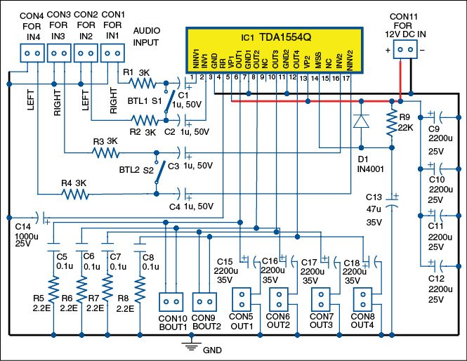
4 Channel Multi Mode Audio Amplifier Circuit Diagram Available

40watts 4 Channel Audio Amplifier Making Electronic Project

Schematic Circuit Electronics 4 Channel Amplifier Circuit

30w 4 Channel Car Amplifier Amplifier Circuit Design

30 Watts 4 Channel Audio Amplifier Electronic Project Using Ta8215ah

Tda7560 4 X 50w Audio Amplifier

Ta8215 4 Channel Power Amplifier Circuit Circuit Diagrams Pinterest
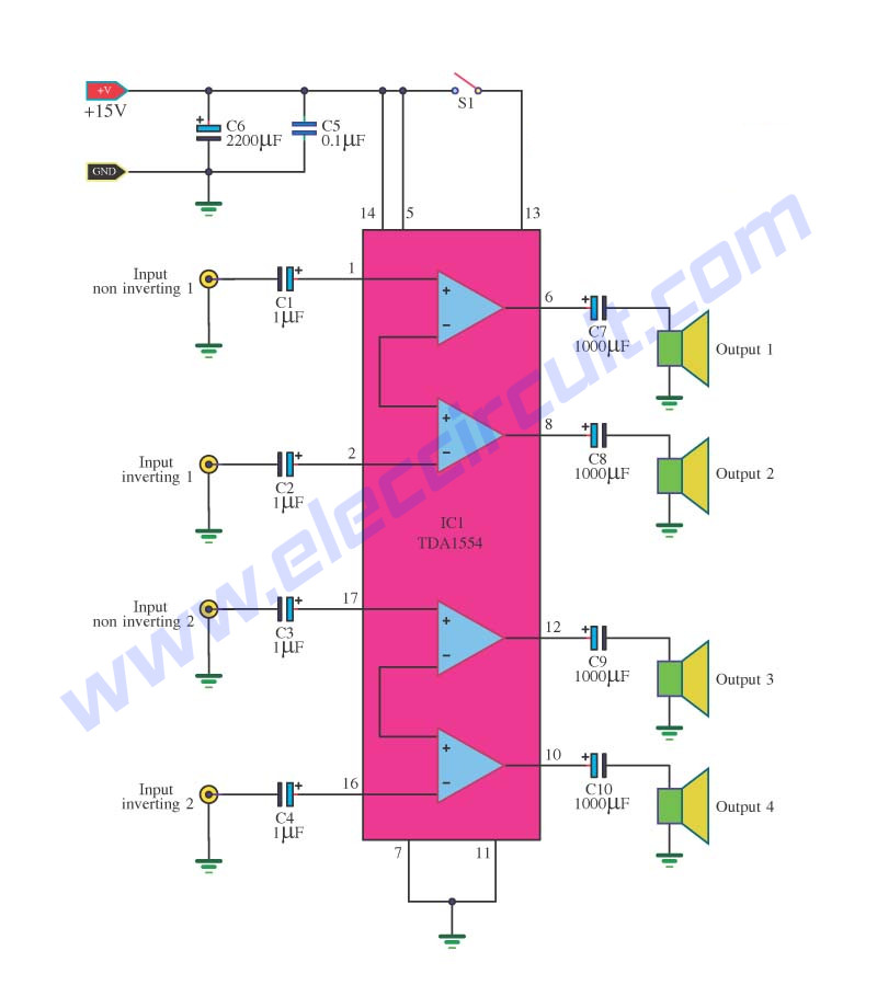
Tda1554 Audio Amplifier Circuits

4 Channel Car Amplifier Using Ta8259h

4 Channel Multi Mode Audio Amplifier Circuit Diagram Available

Making Surround Amplifier Tda7386 4 Channel Home Audio Surround

Ha1377 Two Channel 6 W Audio Amplifier

Jbl Marine Ma6004 4 Channel Power Amplifier Circuit Diagram

Pseudo Balanced Amplifier Pba Headphone Reviews And Discussion

Quadraphonic Amplifier

12 Volt 4 Channel X 55w Amplificator Tda7560 12 Volt 4 Channel X 55w

Audio Amplifiers 4 Channel Amplifier L12251 Next Gr

Simple 4 Channel Video Amplifier Using Njm2582 Circuit Schematic Learn

Ta8215 4 Channel Power Amplifier Circuit Audio Amplifier Circuit

4 1 Channel Amplifier Circuit Board With Bluetooth Receiver V4 0

Amplifier Wikipedia

Wiring Diagram Of Amplifier Wiring Diagram Schema Img

Tda1514 40 Watt Audio Amplifier Circuit

Wiring Diagram Of Amplifier Wiring Diagram Schema Img

Current Channel Circuit Diagram Wiring Diagrams Source
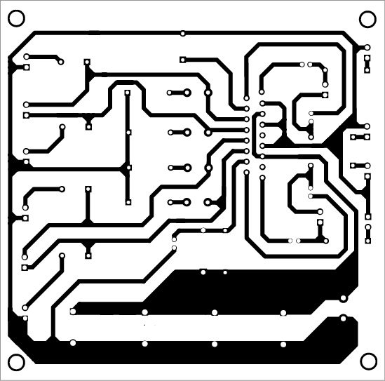
4 Channel Multi Mode Audio Amplifier Circuit Diagram Available

Ta8215 4 Channel Power Amplifier Circuit In 2018 Hobby Electronics

Stereo Speaker Amplifier Wiring Diagram Wiring Diagram Detailed
4 Channel Car Amplifier Circuit Tda1558q Electronics Projects Circuits
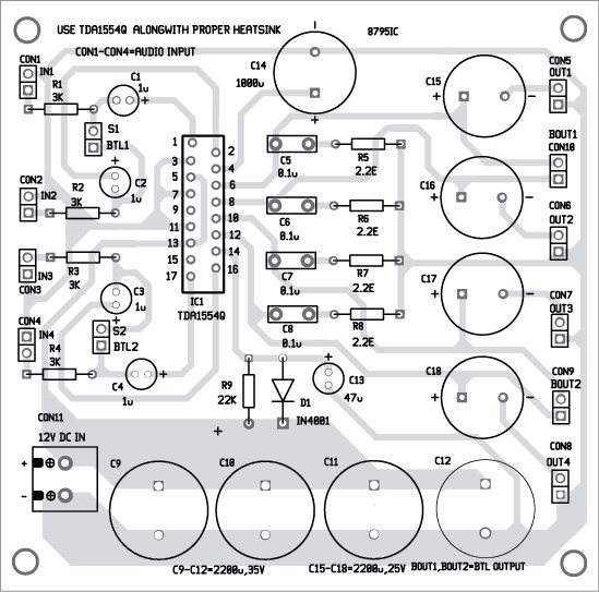
4 Channel Multi Mode Audio Amplifier Circuit Diagram Available

Audio Stereo Circuit Page 3 Audio Circuits Next Gr

2018 New Tda2030a 21 Stereo Amp 2 Channel Subwoofer Audio Amplifier

Amazon Com Pyle Pla4278 4 Channel 2000 Watt Bridgeable Mosfet

Ta8215 4 Channel Power Amplifier Circuit Power Amps Hobby

China Fp10000q 4 Channel Audio Power Amplifier Circuit China Audio

4 Channel Headphone Amplifier 1 4 And 3 5mm Mini 1 8 Stereo Mono

150w Mp3 Car Amplifier

Amazon Com Wingoneer Dc12v 4x41w 2 4 Channel Hifi Tda7388 Amplifier

Audio Mixer Circuit

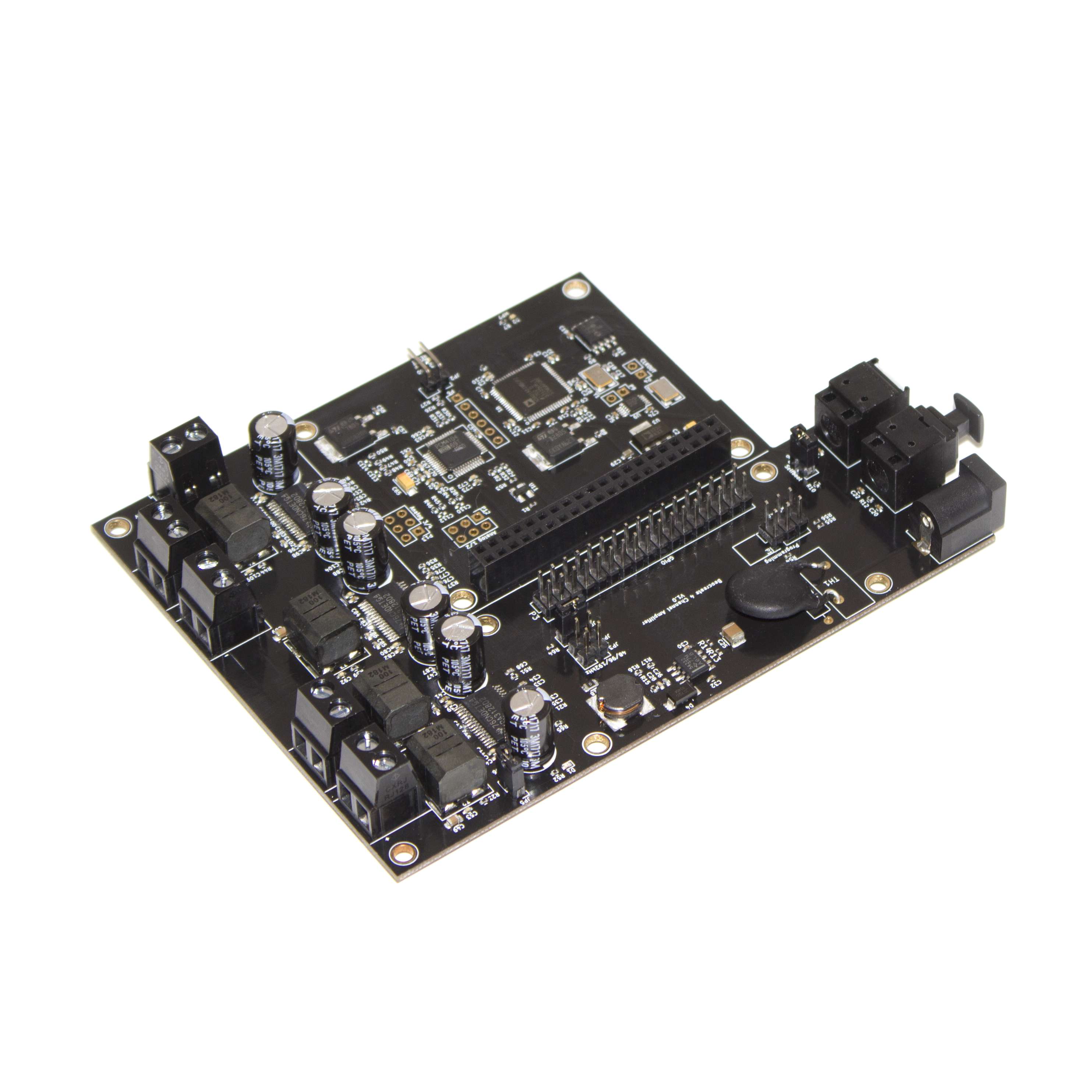
Beocreate 4 Channel Amplifier Hifiberry

Wiring Diagram Of Amplifier Wiring Diagram Schema Img

Current Channel Circuit Diagram Wiring Diagrams Source

Ta8215 4 Channel Power Amplifier Circuit Power Amps Pinterest

Boss 4 Channel Amp Wiring Diagram Alpine Amplifier Sub Wire Data
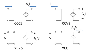
Amplifier Wikipedia

Hi Fi 4 Channel Audio Amplifier Very Simple And Cheap 6 Steps
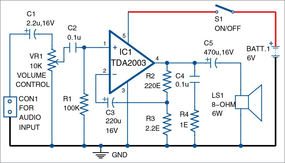
Wiring Diagram Of Amplifier Wiring Diagram Schema Img

Amazon Com Ds18 Gen X3700 4d Full Range Bridgeable 4 Channel 3700w

4 Channel Audio Splitter Audio Distribution Amplifier 4558

20w Audio Amplifier Using Lm1875 Electronic Circuits And Diagram

Tda7388 Amplifier Circuit 4 Channel Power Amplifier Youtube

How To Hook Up 2 Channel Car Lifiers On 2 Channel Amp Wiring Diagram

Simple Audio Channel Circuit Diagram For Fm Transmitter Wiring

150w Mp3 Car Amplifier

Wiring Diagram Of Amplifier Wiring Diagram Schema Img

Circuit Diagram Radio Receiver Browse Data Wiring Diagram

Tida 00573 Automotive 4 Channel Class D Amplifier Reference Design

Amazon Com Lanzar Ev424 Evolution Series 2000 Watt 4 Channel Smd

4 Channel Portable Audio Mixer Circuit Diagram

4 Channel Car Amplifier Diagram Wiring Diagrams

50 Elegant 2 1 Channel Amplifier Circuit Diagram Circuits Diagram

The Best 4 Channel Amps For Sound Quality Top Picks And Buyer S Guide

Aliexpress Com Buy Ta8266hq Ta8266 35w X 4 4 Channel Btl Audio

Circuits Gt Circuit Diagram Of Power Amplifier Electronic Circuits
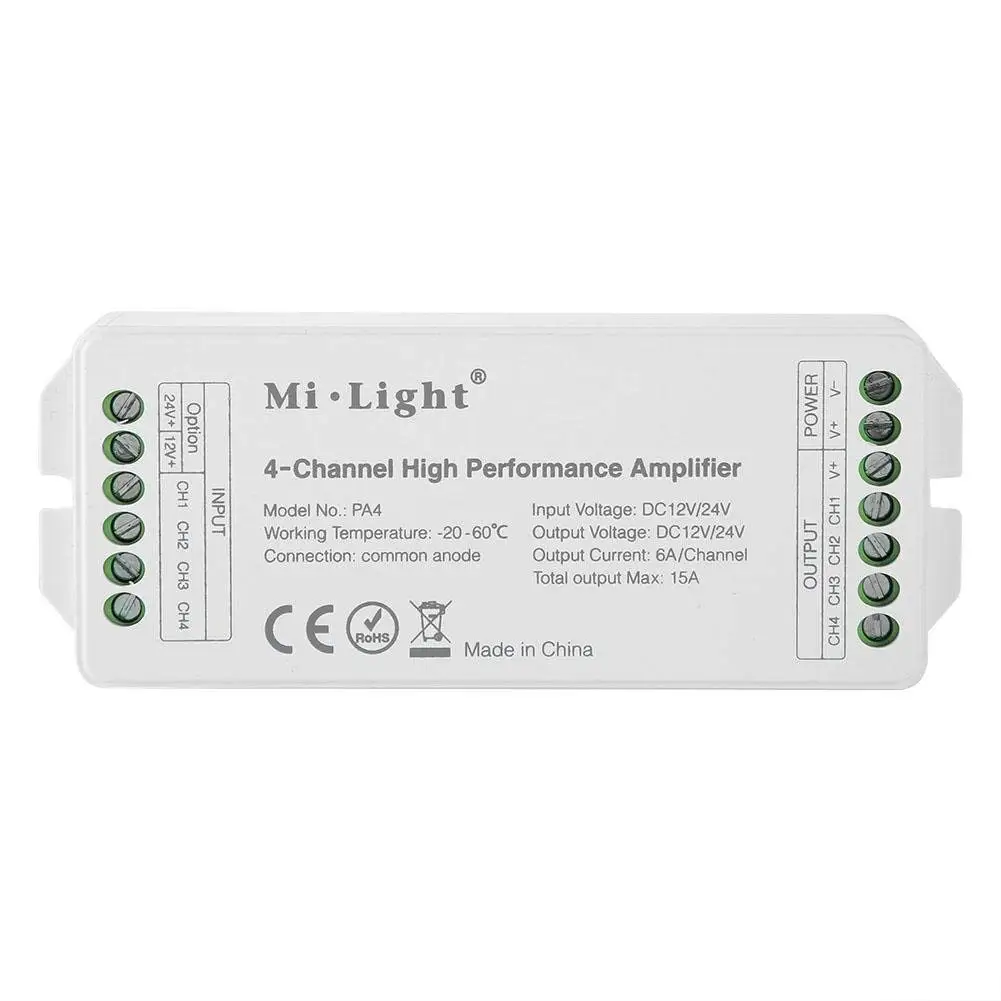
Cheap Output Amplifier Circuit Find Output Amplifier Circuit Deals

Unbeatable Price Pioneer Class Fd 4 Channel Bridgeable Amplifier W
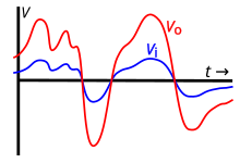
Amplifier Wikipedia

Kicker Dxa250 4 4 Channel Amplifier Fiberglass Circuit Board Car Amp

Mosfet Circuit Diagram Wiring Diagrams Source

Wise Box Receiver 4 Channel 10 Amps Circuit Wireless Radio

Circuit Diagram Radio Receiver Browse Data Wiring Diagram

4 Channel Amplifier With Subwoofer Wiring Diagram Wiring Diagrams

Wiring Diagram Of Amplifier Wiring Diagram Schema Img

Car Amp Wiring Diagram 4 Way Data Wiring Diagram

Circuits Gt Circuit Diagram Of Power Amplifier Electronic Circuits

Car Audio 4 Channel Amp Wiring Diagrams Amplifier Circuit Diagram

Buy Generic 1200w 12v Car Amplifier 4 Channels High Power Amplifier

Amazon Com Yeeco 4x50w Amplifier Board 4 Channel Car Audio

Lm358 Pt100 Circuit Modern Design Of Wiring Diagram

Home Theater Amplifier Circuit Design And Ideas

China Car Power Amplifier Circuit Car Power Amplifier Circuit

2 1 Power Amplifier Using Tda7377 Audio Schematic Pinterest

4 Channel Amplifier Circuit Diagrams Fresh 37 Recent 2000 Watt

Jbl Cs 60 4 4channel Power Amplifier Schematic Circuit Diagram

4 Channel Headphone Amplifier 1 4 And 3 5mm Mini 1 8 Stereo Mono

Electronic Circuit Diagram Audio Indicator Wiring Diagram Home

Amplifier Fp10000q4 Channel Amplifier 4 X 2500 W Power Amplifier
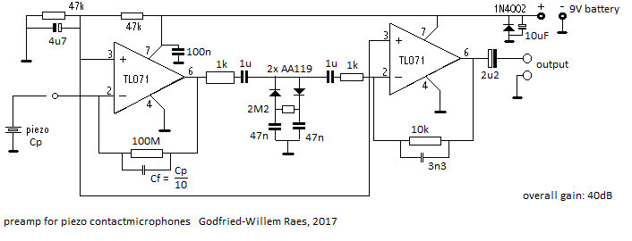
Current Channel Circuit Diagram Wiring Diagrams Source

Galleon Lyxpro Stp10 Compact 4 Channel Headphone Amplifier 1 4

Power Amp Wiring Diagram Wiring Diagram Detailed

4 Channel Alpine Amplifier Wiring Diagram Wiring Diagram Libraries

4 Channel Amplifier Wiring Diagram Awesome Car Audio Amplifier

Electronic Circuit Diagram Audio Indicator Wiring Diagram Home
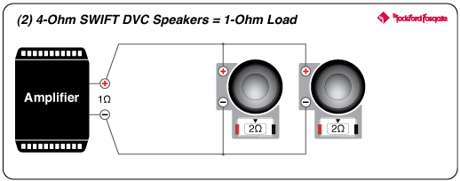
Power 1 000 Watt Class Ad 5 Channel Amplifier Rockford Fosgate

Beocreate 4 Channel Amplifier Review The Magpi Magazinethe Magpi

2016 The Latest 4 Channel Sound Digital Amplifier Fp20000q 2200w

Car Amp Wiring Diagram 3 4 Ohm Multiple Car Amplifier Wiring Diagram


Today Hot Topic