Showing posts sorted by date for query how to wire a car stereo without a harness. Sort by relevance Show all posts
Incredible Wiring Diagram 03 Silverado 2023

Incredible Wiring Diagram 03 Silverado 2023


Incredible Wiring Diagram 03 Silverado 2023. Web 5.3l vin t, engine performance wiring diagram (3 of 5) for chevrolet silverado 2004 1500. Web 7 pin trailer connector wiring diagram tacoma world lights 2020 silverado hd sierra troubleshooting gm trucks com 2018 chevrolet 1500 double cab review edmunds.

2003 Chevy Silverado Headlight Wiring Diagram Collection Wiring
2003 Chevy Silverado Headlight Wiring Diagram Collection Wiring from faceitsalon.com

Web 2003 chevy silverado wiring diagram. Web this video demonstrates the chevrolet silverado complete wiring diagrams and details of the wiring harness. Do you have a from 2002 the diagrams i are only not sha.

17pw26-4 Circuit Diagram

17pw26-4 Circuit Diagram

Fe44010 159 69 3 193 17pw26 4 Circuit Diagram Wiring Resources. 14 Hp Kohler Wiring Diagram.


Vestel 17pw26 4 Service Manual Download Schematics Eeprom Repair Info For Electronics Experts Circuit Diagram Power Math Equations

Vestel 17pw26 4 20445456 Power Supply Pcb Power Supply Power.

17pw26-4 circuit diagram. 17pw25 4 V1 Vestel Psu Repair Youtube. 1995 toyota 4runner fuel system diagram 2007 ram 3500 trailer wiring diagram 17pw26 4 circuit diagram esp wiring diagram gu 04 chevy trailblazer wiring diagram chevrolet chevy 1945 truck wiring electrical diagram dome light wiring diagram 1979 blazer curtis snow pro 3000 wiring diagram 2010 nissan sentra wiring diagram. Can be shipped within 2 days.

110 Cc Engine Electric Start Diagram. 17pw26 4 Circuit Diagram. 32BV502B 32BV504BBoard Model No.

2003 Chevy Trailblazer Rear Fuse Box Diagram. 2003 Chevy Trailblazer Rear Fuse Box Diagram. 100 Amp Panel Wiring Diagram.

17pw15 8 Circuit Diagram. 27 rows reverse engineered psu diagram - primary side. 100 Amp Panel Wiring Diagram.

17pw25 4 Circuit Diagram 65 ford coil wiring auto electrical wiring diagram 17pw25 4 v1 vestel psu repair television manuals free texts free download borrow introductory syriac method and manual by robert dick vestel 17ips20 repair pngline 17pw26 lcd power supply sch pdf document introductory. 2003 Dodge Ram 1500 Stereo Wiring Diagram. 17pw26 4 circuit diagram 05 kia optima wiring diagram tps champion 171 bass boat wiring diagram citroen c3 wiring diagram pdf 01 nissan sentra wiring diagram exhaust fan with light wiring diagram 20 hp kohler engine wiring diagram circuit diagram db9 dexter coin drop wiring diagram.

2002 Mini Cooper Engine Wiring Harness. How To Repair A TV That Wont Turn On How To Repair A TV Power Supply TV Red Light BlinkingLCD TV White Blinking Light Standby Not Turning On Power Sup. Vestel 17mb15 E1 Sch Audio Amplifier Reading Online Read.

Price before VAT plus Delivery. May be help you to repair. 2002 Ford Escape V6 Engine Diagram.

2002 Ford Escape V6 Engine Diagram. 2002 Ford Escape V6 Engine Diagram. 17pw26 4 Circuit Diagram.

2002 Ford Escape V6 Engine Diagram. 664 159 69 3 193 17pw26 4 Circuit Diagram Wiring Resources. 2003 Dodge Ram 1500 Stereo Wiring Diagram.

17pw25 4 Circuit 17 2015 17pw26 4 No Pl815 Socket Vestel Tv. 100 Amp Panel Wiring Diagram. Jan 16 2017 - Manufacturer.

Apply dab electrode gel lead. 2002 Mini Cooper Engine Wiring Harness. Add to shopping basket.

Preview of VESTEL 17PW26-4 1st page Click on the link for free download. 110 Cc Engine Electric Start Diagram. 17pw26 4 Circuit Diagram.

Chevy steering linkage diagram 1990 lincoln town car fuse box diagram wiring 2001 escape v6 engine diagram 17pw26 4 circuit diagram chrysler sebring engine diagram 12 volt wiring diagram for 1956 chevy 1938 mg wiring diagram comcast hdtv hdmi wire diagram electric guitar coil tap wiring diagrams. 14 Hp Kohler Wiring Diagram. REPAIR KIT POWER SUPPLY 17PW25-4 BLOWN Q935 R977 R974.

For this no need registration. VESTEL 17PW26-4 VESTEL 17PW26-4 POWER SUPPLY SCH VESTEL 17PW26 SCH. 100 Amp Panel Wiring Diagram.

2003 Chevy Trailblazer Rear Fuse Box Diagram. Please take a look at the below related repair forum topics. 2003 Dodge Ram 1500 Stereo Wiring Diagram.

14 Hp Kohler Wiring Diagram. 2002 Mini Cooper Engine Wiring Harness. 17pw26 4 Circuit Diagram.

2003 Dodge Ram 1500 Stereo Wiring Diagram. 2003 Chevy Trailblazer Rear Fuse Box Diagram. 2002 Mini Cooper Engine Wiring Harness.

110 Cc Engine Electric Start Diagram. 110 Cc Engine Electric Start Diagram. R865 10k r864 10k tcet110g ic809 1 3 2 4 1k r871 12v 10k r872 24v r875 4k7 r877 33k 47r r873 q813 mtp6n60essp7n60a mtp6n60essp7n60a q814 10r r861 10r r860 c833 100n 50v.

The circuit diagram in Figure 1 shows ICs type LMD18200 and SG3525 at the heart of the circuit. Evh 5150 Gif 4290 3060. 17pw15 8 Circuit Diagram.

17pw15 8 Circuit Diagram. If you want to join us and get repairing help please sign in or sign up by completing a simple electrical test or write your question to the Message board without registration. Brand NewFree UK Delivery - Worldwide From 395.

If you have any question about repairing write your question to the Message board. D latch block diagram circuit diagram led torch 1966 ford mustang v8 wiring diagram chrysler concorde wiring diagram 2009 kia sportage wiring diagram electric bike controller wiring diagram cellular respiration diagram answers 2007 saab 9 3 engine. Vestel 17pw26 Capacitor Component Kit 37 42 Kit.

Smps Power Supply Circuit Diagram Locate The Smps Problem Then. 14 Hp Kohler Wiring Diagram. Chevy 4 wheel drive wiring diagram 2001 passat wiring diagram 2000 bmw 323ci radio wiring diagram circuit diagram components data flow diagram exam system 1995 ford ranger wiper motor wiring diagram 2012 honda ruckus nps50 wiring diagram 2008 ford crown vic fuse box diagram crohns digestive diagram.

17pw15 8 Circuit Diagram.

Wiring Diagram Nc

Wiring Diagram Nc

Miata community wiki nc bosectomy mazda protege headlight wiring 126 mx 5 ls 2005 air con nb dash swap menders diagrams 1990 to mx5 2006 2018 essential owner s manual stereo diagram ecu forum car radio audio work free pdf mazdasd engine control system and repair manuals index of garage conditioning 2009 pictures 2008 factory official service heated seats page 1 seat kit city 3 2003. The new parallel breakout board appears a bit different but the process of wiring and testing is the same.


Ah3 3 On Delay Timer Electrical Circuit Diagram Timer Electrical Engineering Books

Wrg 1056 Nc700x Wiring Diagram.

Wiring diagram nc. If the relay is powered and the switch is closed COM and NO have continuity. This is the terminal where you connect the device that you want powered when the relay receives no power. The normally open auxiliary contact connected in parallel with the two start.

Fritzing Project Relay Test Circuit N O N C. The circuit is from the GND to the input Here is the diagram for the Mach3 USB board pins I1 through I4 are used for input. COM- This is the common of the relay.

No Nc Wiring Diagram wiring diagram is a simplified adequate pictorial representation of an electrical circuit. Service manual on CD for and Honda NCX NCXA NCXD and Honda NC NC. The wiring of the parallel breakout board from the output terminals to the driver digital pulse step pulse and direction lines are explained.

Color Wiring Diagrams IndexHonda Ncx Owners Manual will be a The manual also covers the NCX and has a wiring diagram for it. Nc Switch Diagram Wiring Diagram General Helper Beginning students often find the terminology for switches confusing because the words open and closed sound similar to the terminology used for doors but do not mean quite the same thing when used in reference to a switch. Need wiring diagram from mach3 USB breakout board to inverter.

Wrg 5047 Micro Switch No Nc Wiring Diagram. Vfd is a short form of variable frequency drive or variable voltage variable frequency driveThe VFDs are working based on changing the input frequency and input voltage of the motor we can change the speed of. How about a diagram to reference showing the pin-out to use Here is the diagram for the parallel breakout board pins 10 through 13 are used for input.

Wrg 1056 Starter Push On Wiring Diagram. VFD Start Stop Wiring Diagram. The device connected to NC will be on when the relay has no power and will turn off when the relay receives power.

Whether its practical DIY home-improvement tips gadgets and digital technology information on the newest cars or the latest breakthroughs in science -- PM is the ultimate guide to our high-tech lifestyle. Us 12 01 11 Off Universal Motorcycle Turn Signal Light Indicators Amber Led Lights For Honda Vfr Nc 700 750 800 1200 F Vfr750 Vfr800 Vfr1200 On. A wiring diagram is a simple visual representation of the physical connections and physical layout of an electrical system or circuit.

The wiring of the parallel breakout board from the output terminals to the driver digital pulse step pulse and direction lines are explained. Circuit Diagram Nc Wiring Diagram 500. So first identify the magnetic coil terminals where the power supply is to be applied.

NC- This is the Normally Closed Switch. MC Motor Starter Wiring Diagram With CB MC OL NO NC The symbol diagram is best but everyone cant understand it easily that why I always focus on imagediagram which easy and simple to understand and good for learning. Scanner Scantool Obdi Obdii Obd2 Automotive.

Wiring diagram a wiring diagram shows as closely as possible the actual location of all component parts of the device. Motor Wiring Diagram 3 Phase 10 Wirepdf. You can get the terminal identification or internal circuit diagram of every relay printed on their body or their user manual.

1980 honda nc50 wiring diagram moped wiki army express uk schematic 4 stroke net all the data for your motorcycle and us diagrams here s help adding turn signals to yamaha qt50 luvin other nopeds manual na50 ii rebuild tbolt usa tech database llc myrons mopeds 1977 1983 na scooter custom motorcycles 1981 wire harness ignition coil battery 81 parts grommet b main pipe d order at cmsnl wtb. Micro Switch No Nc Wiring Diagram. Operation of your CNC or automated machinery.

Now identify Normally Closed contacts terminals then Normally open contacts terminals. Open and close switch wiring diagram. I am here with giving you a VFD start stop wiring diagram for running a VFD through panel board push button and keypad of the VFD It is called HMI.

Blesiya No Nc Kunci Elektrik Piring Gagal Secure Dan Gagal Aman Pelat Strike Pintu Kunci. Motor Wiring Diagram 3 Phase 10 Wirepdf speedcontrol SC wires Q1 and Q2 to terminal 41 mod 2 link for torque seated valve 3 motor wiring 59 21. It shows the components of the circuit as simplified shapes and the capability and signal contacts between the devices.

Auxiliary contact no nc 10 01 10 01 10 01 10 01 10 01 11 11 11 11 11. The below diagram setting is base on 5mm screw pitch and excitation mode is 18 mircostepping. What does this symbol mean this wiring diagram.

Sometimes the contact point a is called no contact point and the contact point b is called nc contact point however the jis c 0301 graphical symbols for diagrams prescribes them as contact point a and contact point b respectively. NC no no ts close 9 14 e u lb n e e r g com NC NC ls 2 open without Page 826 3916848. Grbl Homing Using Nc Switches Class B Project.

Acces PDF Honeywell Fan Center Wiring Diagram Popular Mechanics inspires instructs and influences readers to help them master the modern world. 61mgs03 2012 2015 Honda Nc700x Xd Motorcycle Service Manual. For assembly and wiring diagram of the interlocked contactors refer to.

Sw Intlk No Nc Snap Mt. Go to the new parallel breakout board to get more information and the wiring diagram. But you know that this diagram designing takes bag time from the time of the symbol diagram.

Circuit Diagram Nc Wiring Diagram Table. Nc700x Fuse Box Wiring Diagram. My 37 year old 77 gs is apparently more powerful than a will give you a solution for you to Honda NCX Owners manual.

Wiring Diagram Kenwood Radio

Wiring Diagram Kenwood Radio

Kenwood car radio wiring diagrams. It shows the components of the circuit as simplified shapes and the capacity and signal links amid the devices.


Car Stereo Wiring Harness Diagram Pioneer Car Stereo Sony Car Stereo Car Stereo

As stated earlier the traces at a Kenwood Radio Wiring Diagram represents wires.

Wiring diagram kenwood radio. Kenwood wiring diagram colors Wiring Diagram For Kenwood Deck Valid Radio Colors Database Harness Color. A wide variety of kenwood radio wiring harness options are available to you such as application. Dual camera function explained on the kenwood reverse wiring diagram cmos 130 backup safety 230 universal how to install a double din flickering archives installing rear view base overclockers uk 15 back up yotatech ddx276bt stereo with bypass pac rp5 gm11 320 installation in first gen tundra.

Step by step installation instructions complete with photos tool list and wiring detail. Interconnecting wire routes may be shown approximately where particular receptacles or fixtures must be upon a common circuit. Wiring Diagram Pics Detail.

This service manual can be obtained from kenwood upon inquiry. Whether your an expert hyundai mobile electronics installer hyundai fanatic or a novice hyundai enthusiast with an hyundai a hyundai car stereo wiring diagram can save yourself a lot of time. KENWOOD Car Radio Stereo Audio Wiring Diagram Autoradio connector wire installation schematic schema esquema de conexiones stecker konektor connecteur cable shema car stereo harness wire speaker pinout connectors power how to install.

2-12 VOLT IGNITION WIRE. But it doesnt imply connection between the wires. Kenwood kdc mp242 radio cd support and manuals.

Kd R300 Stereo And Jvc Kd-R300 Wiring Diagram Wordoflife inside Kenwood Kdc 200U Wiring Diagram image size 765 X 990 px. Top plate fcc warning this equipment may generate or use radio frequency energy. Top plate how to read this manual.

Injunction of 2 wires is generally indicated by black dot in the junction of two lines. Kenwood Car Radio Wiring Diagram Bo 0972 Vehicle Radio Wiring Diagrams Schematic Wiring - What do the colors on your wiring harness mean. Tigertronics has not verified the accuracy of all of the radio wiring information that is provided here.

At times the cables will cross. The side filler panels clips. Sometimes the cables will cross.

READ Dump Trailer Hydraulic Pump Wiring Diagram Gallery. Kenwood Ddx376Bt Wiring Diagram. KENWOOD KDC-7070R KDC-5040R KRC-958R.

Kenwood Ddx470 Wiring Harness Colors Wiring Diagram Detailed Kenwood Radio Wiring Diagram In addition Wiring Diagram gives you time body in which the assignments are to become accomplished. Kenwood Radio Wiring Diagram. As stated previous the lines at a Kenwood Car Stereo Wiring Diagram signifies wires.

You may be capable to know exactly if the projects should be finished which makes it much easier for you personally to effectively control your time and effort. A custom wiring harness or T-connector is a vehicle-specific harness that plugs in without any spicing required and provides a standard connector output Find the trailer light wiring diagram below that corresponds to your existing configuration. Variety of kenwood wiring diagram.

These adaptors are made to make it easy to connect your new stereo to the cars existing clip. Injunction of two wires is usually indicated by black dot in the intersection of 2 lines. View and download kenwood tk 2180 service manual online.

2018 Civic Lx Kenwood Audio Receiver Install Page 5 Honda Forum 10th Gen Type R Si Civicx Com. Kenwood Car Radio Stereo Audio Wiring Diagram Autoradio Connector Wire Installation Schematic Schem 3u文域. Kenwood Car Radio Stereo Audio Wiring Diagram Autoradio Connector Wire Installation Schematic Schem 3u文域.

Kenwood car stereo wiring instructions head unit dmx125bt digital multimedia 4 channel amp to speakers and a sub kdc x898 user manual owner s diy how install subwoofer with excelon dmx706s consumer electronics new wire harness hd545u. Refer to the model and serial numbers whenever you call upon your kenwood dealer for information or service on the product. Kenwood Ddx374bt Wiring Diagram Wiring Schema It shows the components of the circuit as simplified shapes and the power and signal connections amongst the devices.

Kenwood Radio Wiring Diagram wiring diagram is a simplified suitable pictorial representation of an electrical circuit. But it doesnt mean link between the wires. Kenwood stereo and speaker wiring colors are.

16 pin kenwood kdc hd942u mp142 car stereo head unit madcomics ddx wiring diagram radio audio 252u full corporation compact disc 138 aftermarket owner s manual wire colors install 352u instructions vehicle mp208 mp238 139 mp239 248u instruction pdf 448u cd. Kenwood Kdc 200U Wiring Diagram pertaining to Kenwood Kdc 200U Wiring Diagram image size 395 X 640 px Description. Every buick stereo wiring diagram contains information from other buick owners.

KENWOOD Car Radio Stereo Audio Wiring Diagram. Architectural wiring diagrams discharge duty the approximate locations and interconnections of receptacles lighting and long-lasting electrical services in a building. Kenwood wiring diagram colorsFree car stereo and car radio installation resource.

Raider J Wiring Diagram

Instrument panel fuse block gmc yukon. Instrument panel suzuki 125 service manual pdf download manualslib suzuki raider 150 37.


Dazon Raider Classic Wiring Diagram Wiring Diagram 150cc Engine Diagram

DAZON RAIDER CLASSIC - SERVICE MANUAL- English Service Manual and Wiring Diagram to buggy Dazon Raider Classic CONTENTSSERVICE Raider-Classic Oil-cooledInternal Gearbox.

Raider j wiring diagram. Suzuki skydrive electrical wiring diagram. Suzuki Raider J 110 Wiring Diagram Effectively read a wiring diagram one provides to learn how the components within the method operate. Wiring Diagram Of Suzuki Raider 150 Chapter 1.

This is a Wiring Harness Guide for Suzuki Smash Raider J ShogunRPro Motorcycles. Posted on Apr 02 2019. Wiring Diagram Of Suzuki Raider 150 gmc yukon 2003 - 2004 - fuse box diagram - auto genius gmc yukon 2003.

Raider R150 Wiring Diagram. You can see that a SPST toggle switch only has 2 terminals. View 2011 SUZUKI RAIDER J PRO 110 manual type for sale in Dasmarinas on OLX.

October 1966 marked the first year for the companys debut beautiful road racing motorcycle Suzuki 250 T20. It was equipped with an unusual then separate lubrication. 1 terminal is Marine Raider illuminated Toggle 3 position - Texas Fishing ForumHow to Wire a Toggle Switch It Still Runs.

Mga ka diy subscribe n like po ang aking yo. 1991 yamaha 115 wiring diagram 115 wiring diagram. When you use your finger or even the actual circuit together with your eyes it may be easy to mistrace the circuit.

Diagram suzuki raider 115 fi wiring diagram full version hd quality wiring diagram. Equipped with RAIDER J PRO. Whether its a short or long ride it will handle the demand with ease.

Prior on my post with the FL125 shogun electrical wiring diagram in by request wanting to have the diagram of raider r150. CDI ORANGE - from Ignition ACC BLACKswhite - Ground WHITEsblue - to Ignition Coil BLUEsyellow - to ENGINE Stator side ENGINE - Stator Single Phase WHITEsred - To RECTIFIER YELLOWswhite - To RECTIFIER. Original suzuki rectifier for shogun smash raider j150 skydrive.

An expert who has achieved level 1. However it does not possess as sophisticated and electric intensive characteristics that RV and other costly trailers may have. Some SUZUKI Motorcycle Manuals Wiring Diagrams PDF are above the page - B andit Burgman DL GR FA FX Haybusa Intruder Marauder PE Raider SVT500 V-Storm Volusia VL.

The one posted below uses the 103 990 key switch and although it isnt a Raider 14 diagram it would do the trick for your tractor. Circle J Horse Trailer Wiring Diagram Wiring Diagram Libraries Circle J Trailer Wiring Diagram by Bismillah. Raider 150 Suzuki PDF File.

We will now go over the wiring diagram of a SPST Toggle Switch. Or find more 2nd Hand Used 2011 SUZUKI RAIDER J PRO. Service Manual single double-seat EEC Version.

Suzuki Raider J 110 Wiring Diagram wiring diagram is a simplified good enough pictorial representation of an electrical circuit. CDI ORANGE - from Ignition ACC BLACKswhite - Ground WHITEsblue - to Ignition Coil BLUEsyellow - to ENGINE Stator side ENGINE - Stator Single Phase WHITEsred - To RECTIFIER YELLOWswhite - To RECTIFIER. All bikes have a color coded wire for easy tracing when doing electrical works.

This is a Wiring Harness Guide for Suzuki Smash Raider J ShogunRPro Motorcycles. For instance in case a module is powered up and it sends out a signal of half the voltage plus the technician will not know this he would think he provides a problem as he or she would expect a 12V signal. An expert that has 1 follower.

Below is the wiring schematic diagram for connecting a SPST toggle switch. Suzuki R150 Raider wiring diagram. Diagram Suzuki Raider J Pro Wiring Full Version Hd Quality Diagramman Prolococusanese It Suzuki Car Radio Stereo Audio Wiring Diagram Autoradio Connector Wire Installation Schematic Schema Esquema De Conexiones Stecker Konr Connecteur Cable Shema.

Making modification on raider R150 electrical is difficult without the right electrical diagram. Posted May 3 2020. Suzuki Raider150 The 2014 Suzuki Raider J 115 Fi and all other motorcycles made since 1970.

Print the cabling diagram off and use highlighters to trace the signal. In terms of comfort the Suzuki Raider 150 has a well-cushioned seat ensuring riders comfort. Suzuki Raider 150 Cdi Wiring Diagram from wwwcarknowledgeinfo.

Disclaimer lang po di po ako pro mechanicTinuturo ko lamang po kung ano ang aking nalalaman tungkol sa wirings. The electrical diagrams I posted are primarily intended to show how the various components in the wiring work together. Feb Lubrication System General Introduction The picture shows the functional diagram of the lubrication system.

It may also be applicable to Hayate Step Mola and Raider 150. Suzuki alto electrical wiring diagram. How to convert raider j cdi to raider 150 reborn.

This 5-pin trailer wiring diagram is great for trailer that has big capacity. A06 2012 Yamaha Raider Wiring Diagram Wiring Resources Ad20fb Fuse Box Diagram 1979 Yamaha 1100 Wiring Resources C 11 Cyclone Talking Alarm Final Wiring Diagram For 2 Wire System 219c7 2009 Yamaha Raider Wiring Diagram Digital Resources Gl500 Wiring Diagram As Layers Download If Useful Honda Cx Yamaha Oem Turn Signal Connectors 3 Wire Pair Custom Led Gy6 150cc Cdi Wiring Diagram. It may also be applicable to Hayate Step Mola and Raider 150.

It shows the components of the circuit as simplified shapes and the knack and signal friends with the devices. Suzuki rf600 electrical wiring diagram.

Wiring Diagram 2006 Chevy Silverado

Wiring Diagram 2006 Chevy Silverado

A wiring diagram usually gives guidance roughly the relative twist and. Sometimes the cables will cross.


1994 Chevy Silverado Wiring Diagram Fuse Box And Wiring Diagram In 2021 Chevy 1500 Chevy Silverado Truck Stereo

2006 chevy silverado trailer wiring diagram You will need an extensive expert and easy to know Wiring Diagram.

Wiring diagram 2006 chevy silverado. May 02 2011 814pm. Ignition Coil Circuit Wiring Diagram 2003 2006 V8 Chevrolet Silverado Gmc Sierra. 2006 Chevy Silverado Radio Wiring Diagram wiring diagram is a simplified customary pictorial representation of an electrical circuitIt shows the components of the circuit as simplified shapes and the capability and signal connections together with the devices.

With this kind of an illustrative manual you will have the ability to troubleshoot prevent and total your assignments easily. 2005 Chevrolet Silverado 1500 Owners Manual. Otherwise the arrangement wont.

2006 Chevrolet Silverado 1500 Owners Manual. Assortment of 2006 chevy silverado radio wiring diagram. It really is supposed to aid all the common user in developing a proper system.

When you use your finger or follow the circuit along with your eyes it is easy to mistrace the circuit. 2006 Silverado Wiring Diagram Cars. 2002 Chevrolet Silverado 1500 Owners Manual.

I have searched site and cant find help on locating total wiring diagram for Fog lamps to dash switch help Re. 1999 Chevrolet Silverado 1500 Owners Manual. 2006 Pontiac G6 Radio Wiring Diagram Inspirational Cobalt Wiring.

A single trick that I actually use is to print out exactly the same wiring picture off twice. 2006 chevy silverado tail light wiring diagram Youll need a comprehensive professional and easy to understand Wiring Diagram. With such an illustrative guidebook youll be capable of troubleshoot stop and total your tasks without difficulty.

2006 53ltr chevy silverado z71 p0455 andp0449 These codes are for the evaporative emission systemThe 455 is the vent solenoidThe 455 is a large leak in the evapsystemThe vent solenoid I would replace because they go bad and will not work because they are under the vehicle in the rear of the truckThere is a bulletin for these and the vent valve is installed in another spotThe. Otherwise the structure will not work as it. When you make use of your finger or even the actual circuit along with your eyes it is easy to mistrace the circuit.

Wiring Diagram 2006 sierra crew. 2002 Chevy Silverado Wiring Diagram Truck Stereo Chevy Impala. It shows the parts of the circuit as streamlined forms as well as the power as well as signal connections between the devices.

2004 Chevrolet Silverado 1500 Owners Manual. Print the wiring diagram off in addition to use highlighters to trace the signal. Pink left front speaker wire.

Wiring Diagram arrives with numerous easy to stick to Wiring Diagram Instructions. 4l60e Transmission Fuse Location Unique Wiring At 4l60e Diagram. 1981 Chevy Truck Wiring Diagram The 1947 Present Chevrolet Gmc Message Board Network.

Orange radio ground wire. 2013 Chevy Wiring Harness Diagram All Wiring Diagram Data Chevy Silverado Wiring Harness Diagram. These instructions will likely be easy to grasp and implement.

2006 Chevy Silverado Tail Light Wiring Diagram wiring diagram is a simplified up to standard pictorial representation of an electrical circuit. Wiring Diagram 2006 sierra crew. 2006 Chevy Silverado Tail Light Wiring Diagram 2006 chevy silverado brake light switch wiring diagram 2006 chevy silverado brake light wiring diagram 2006 chevy silverado tail light wiring diagram Every electric structure is composed of various unique components.

Chevy Wiring Diagrams. Whether your an expert Chevrolet Silverado C1500 mobile electronics installer Chevrolet Silverado C1500 fanatic or a novice Chevrolet Silverado C1500 enthusiast with a 2006 Chevrolet Silverado C1500 a car stereo wiring diagram can save yourself a lot of time. May 02 2011 849pm.

Chevrolet car radio stereo audio wiring pinout diagram for a gm factory chevy silverado 2001 suburban 2000 tahoe hhr network looking and pin outs 2004 bose 2006 tail light 2005 pink wire speaker system need how are pillar tweeters wired from 2003 2007 amplifier guide to harnesses 12 plug 2011 1500 chart an amp sub stock aftermarket in. Each component ought to be set and linked to other parts in specific manner. Print the electrical wiring diagram off in addition to use highlighters to trace the signal.

2006 Chevy Silverado Trailer Wiring Diagram Folks comprehend that trailer is a car comprised of rather complicated mechanics. Assortment of 2006 chevy silverado wiring diagram. Headlight And Tail Light Wiring Schematic Diagram Typical 1973 1987 Chevrolet Truck Chevy Chuck S Pages.

This car is designed not only to travel one location to another but also to carry heavy loads. A wiring diagram is a simplified traditional pictorial representation of an electric circuit. Chevy Truck Forum Silverado Sierra GMC Truck Forums.

A wiring diagram is a simplified traditional pictorial representation of an electric circuit. 1990 Chevy Silverado Radio Wiring Diagram Di 2020 Dengan Gambar. How To Chevy Silverado Stereo Wiring Diagram.

2003 Chevy Radio Wiring Diagram Truck Stereo Chevy Impala Impala. Each part should be set and connected with different parts in particular way. It shows the components of the circuit as simplified shapes and the facility and signal links together with the devices.

This guide will be discussing 2006 chevy silverado trailer wiring diagramWhich are the advantages of understanding these understanding. Automotive wiring in a 2006 Chevrolet Silverado C1500 vehicles are becoming increasing more difficult to identify. 2003 Chevrolet Silverado 1500 Owners Manual.

2006 Chevy Silverado Radio Wiring Diagram 06 chevy silverado stereo wiring diagram 2006 chevy silverado 2500 radio wiring diagram 2006 chevy silverado bose radio wiring diagram Every electrical arrangement is made up of various unique components. Gray right front speaker wire. One trick that We 2 to print the same wiring picture off twice.

2006 Chevy Silverado Turn Signal Wiring Diagram.

Xprog-m Schematic Diagram

And inside missing some parts. Notice that Xprog is presetting the clock as 419 Mhz for this chip if you use 4Mhz reset it to 4MHz too.


Launch X431crp909e Obd2 Diagnostic Scanner Professional Obd2 Car Scanner Airbag Ebay In 2021 Car Scanner Obd2 Scanner

Citroen C2 16L Bosch MP744 K-Line Yes Yes Checksum Button.

Xprog-m schematic diagram. Citroen C2 14 HDI Siemens SID 804 K-Line Yes Yes Yes. Where to find wiring diagram mbworld org forums mercedes free resources mb medic w203 for electronic ignition switch eis control unit d4pqg507mdnp c300 headlight full version hd quality codiagram amicideidisabilionlus it obd2 ezs xprog m here facebook benz fuse box c320 rediagram back up camera help washer pump level sensor Where To Find Wiring Diagram Mbworld Org Forums. - schematic diagram of the XPROG-m programmer color and gray version - datasheets for all semiconductors - high-quality photos both sides of the PCB - XPROG-BOX to XPROG-m downgrade instruction - ATmega64 firmware - transparent instruction set fusebits.

R LASER PRINTER PART. Free Download OEM Orange5 v134 software and adapter schematics May 5 2016 uobdii ECU ProgrammerChip Tuning Tool 0 Free download original or clone OEM Orange5 programmer v134 software and adapter list schematics and immo list here. With U8 and U10 no problem.

Scribd is the worlds largest social reading and. We have it here on obdexpresscouk. Original Brand Universal Chip Programmers Device made in China including.

Model-ECU-engine type read-write-Auto Checksum. Documentation for the XPROG-m programmer. AVR ISP API on Linux version need the parport parport_pc and ppdev kernel modules.

Mercedes benz w203 s203 cl203 2000 2007 audio 20 mf2530 head unit pinout diagram pinoutguide com car radio stereo wiring autoradio connector wire installation schematic schema esquema de conexiones stecker konr connecteur cable shema 10 amplifier b74 sight gti full version hd quality outletdiagram visualpubblicita it comand 2 c din android steering wheel control can bus. Citroen Berlingo 20 HDI Bosch EDC15C2 K-Line Yes Yes Checksum Button. How to install Yamaha immobilizer emulator.

Brother HL-1660 Parts Manualpdf. AND a xtal of about 4MHz to pin 1 and 52 together with a resistor of about 5-10 Mohm to the same pins. Fixed some bugs and added marking elements.

Write good dump 3. Erase EEPROM 4096bytes 2. Finally I publish the final version of XPROG schematic diagram rev.

To select it choose Easy I2CBus from the Options - Setup menu and the parallel checkbox. As the chip has been removed follow the manual diagram 217. ECU Programmer Iprog Schematics Download Free.

Hi I got not working xprog 584. Flash with correct zusb number for your vehicle using winkfp. 2006-2009 years Yamaha bikes and scooters motor ECU immobilizer functionWorks with YFZ R1 R6 X-MAX T-MAX V-MAX and others.

Choosing the ECU type and the CPU chip type to view the wiring diagram and read the ECU data. Without dismantling the ECU ktm bench pcmflash 199 can read all 71 ECU data by connecting to the. XPROG-m - Schematic diagram rev Bpdf - Free download as PDF File pdf Text File txt or view presentation slides online.

Verify obd working and change vin VO as if retrofitting used FRM3. XPROG-M R270 ORANGE5. JDM schematics How to connect 24Cxx eeproms to JDM programmer.

My collection of FRM3 dumps p-flash and EEPROM. Mercedes car radio stereo audio wiring diagram autoradio connector wire installation schematic schema esquema de conexiones stecker konr connecteur cable shema benz w203 s203 cl203 2000 2007 20 mf2530 head unit pinout pinoutguide com speaker electro circuit 10 menulisitukerjaaku comand 2 sakuraaiman c230 harness for mbworld org forums c clk w209 2004 gps. To connect to the MCU there are 3 methods Im aware.

On Windows2000XP you have to select AVR ISP IO and use a standard PC LPT port. Immobilizer emulator for Yamaha bikes. Here is a picture that explains everything about how to program the ATMEGA64 repair chip in XPROG with UPA-USB programmer.

April 21 2020 sales Car diagnostic tool Software downloadUpdate 0. Brother HL-1660 Parts Manualpdf. Please help with U4.

About some users requesting schematic of iprog. 06-21-2020 0935 AM dinho Wrote. Easy I²C Bus interface.

Try to conect all wires manually. Problema nu s-a rezolvat am rescris atmega si 93lc46 cu binurile postate de vasi in schimb cand dau citire spune device is silentunde am gresit. This is a DIY user manual of immobilizer emulator for Yamaha bikes including models supported installation instruction and wiring diagram.

Brother HL-1660 Parts Manual. Citroen Berlingo 20 HDI Siemens SID 801801A K-Line Yes Yes Yes. First come with the connection of KTM Bench to the computer and the ECU.

XPROG-m - Schematic Diagram - Free download as PDF File pdf Text File txt or view presentation slides online. Chip programmer IC programmer EPROM programmer Flash programmer ISP programmer PIC programmer Production Programmer and bios programmer online shopping store. Cant recognise chip U4.

There are 2 tips to properly use KTM Bench to read write the ECU data.

Wiring Diagram Color Codes

Wiring Diagram Color Codes

UK AC power circuit wiring color codes US AC. Ground - Ground wiring should be green or green with a yellow stripe.


Uk Electrical Power Cable Color Code Wiring Diagram Color Coding Electrical Cables Electricity

Assortment of automotive wiring diagram color codes you are able to download totally free.

Wiring diagram color codes. Phase 3 - Phase 3 wiring should be yellow. This article describes the new electrical cable color code wiring diagram ac and dc in United StatesukCanadaEurope for single phase or three phase In Electrical engineering different wires. Interconnecting wire routes may be shown approximately where particular receptacles or fixtures must be upon a common circuit.

Bmw wiring colour codes wiring diagram inside Architectural wiring diagrams show the approximate locations and interconnections of receptacles lighting and surviving electrical services in a building. Please validate all cord colors and representations before using any kind of info. Yamaha Vega Engine Diagram Motor Yamaha.

The US National Electrical Code only mandates white or grey for the neutral power conductor and bare copper green or green with yellow stripe for the protective ground. Here are the headphone wire color codes for a three-cable headphone. Free car radio wires stock diagram.

Following table illustrates which pin is sending and which is receiving data. Ford Wiring Color Codes Top Electrical Wiring Diagram Wiring color codes are virtually the same across all models and years. Cat6 Wiring Diagram Color Codes - Wiring Diagram is the graphical depiction of a complex electrical circuit.

Wire Color Codes For USA Phase 1. B Black Br Brown Ch Chocolate Dg Dark green G Green Gy Gray L Blue Lg Light green O Orange P Pink Red Red Sb Sky blue W White Y Yellow BG BlackGreen BL BlackBlue BR BlackRed BW BlackWhite BY BlackYellow BrG BrownGreen. S10 blazer diy and useful threads wiring color codes 82 93 s 10 or blazer 12volts red there will be 2 ignition harness starter yellow or purple ignition harness ignition pink ignition harness second ignition white ignition harness accessory orange ignition harness second accessory brown.

The Red color cable is the right signal The BlueGreen color cable is the left signal The CopperGold color or. How to hack a headphone jack earphone with mic wire color code off 64 kingston hyperx cloud ii skullcandy ink d 2 audio 5 wires red golden blue green usb headphones wiring diagram full klipsch s4i repair broken earbud diffe of earphones gaming headset salvage cables and glowing mod what do these colours connection 61 flat for 3 5mm jacks plugs work cable new replace plug harley diagrams. 30a fuse for the wiper motor relays and wiper motor 15a fuse for the washer motor relay and washer motor 10a fuse for the low current board in the sjc to receive the washer signal from the mfs and provide ground to the washer relay.

Neutral - Neutral wires should be grey. These are the wire color coding standards that are used in the United States. Need to the electrical wiring diagram and shade codes to need to the electrical wiring diagram.

Home Uncategorized Motorcycle Wire Color Codes. On this web page we offer you the decoding of the bmw color codes. Wiring diagrams help technicians to determine how the controls are wired to the system.

Wiring Diagram Harley Davidson Wiring Color Codes. Color code for wiring diagram. Motorcycle Wiring And Electrical Repair Tips Motorcycle Cruiser.

T568A Wiring diagram. Wiring Color Code For Ceiling Fan Zen Diagram Send104b. Electrical cable Wiring Diagram Color code Posted by VLOG AGADIR Posted on 1148 AM with 278 comments Look for a house Electrical wire color code guide.

You simply need to have a great comprehension on different kinds of wiring and their purposes. Please download these automotive wiring diagram color codes by using the download button or right click on selected image then use Save Image menu. The Wiring Diagram is typically used in electric engineering to intend the placement of electric circuits.

Nissan radio cable harnesses and cord colors. Phase 2 - Phase 2 wiring should be orange. Electric Wire Color Code Us Perfect Nissan Wiring Diagram Color Based on all the different wiring diagrams shown here 22 liter with and without cng with and without an immobilizer or a 30 liter with or without california emissions youre simply not going to find the right wiring diagram for free online.

In principle any other colors. White Ground wire is either a Green wire a Bare Wire or a Green wire with Yellow Stripe. Home Wiring Plan Software Making Wiring Plans Easily.

On the wiring diagram Ground wire is also on the diagram right side and goes also to HDI position lamp is on the bike and HDI position light power is from connector 38B pin 1 OW etc. This color coding standard was introduced in mid of 1980s its not widely used these days. It is extremely easy to attract a wiring diagram.

April 03 2021 Read. Posted on August 2 2012 by janpenguin. Below is a simple light switch wiring diagram if needed.

Basic Electrical For Wiring For House Wire Types Sizes And Fire Alarms. NEC Wiring Color Codes for AC US Canada US NEC AC Single Multi-Phase Wiring Color Codes The mandatory colors for power wiring in National Electric Codes NEC are Green Bare or GreenYellow Yellow Strip or band on Green for Protective Ground PG and White alternatively Grey for Neutral Wire. 02 nissan frontier ignition electrical wiring diagram.

Ford motor wiring color code. Below is straight through wiring diagram of 568A color coding. Malaysian Grid Code Tenaga Nasional Berhad.

Astra H Wiring Diagram Download

Astra H Wiring Diagram Download

Holden Astra Fuse Box In Engine Bay Ah Sri 2 0ltr. Opel Car Pdf Manual Wiring Diagram Fault Codes Dtc.


Elegant Wiring Diagram Astra H Diagrams Digramssample Diagramimages Wiringdiagramsample Wiri Electrical Wiring Diagram Trailer Wiring Diagram House Wiring

Opel Astra H Astra Twintop 2010 2012 Fuse Box Diagram.

Astra h wiring diagram download. Black Front Wiper Windscreen Motor For Vauxhall Astra G Mk4 98 04. The vauxhall combo introduced in 1993 by german automaker opel is a leisure activity vehicle. In europe holden combo.

Spanish astra wiring diagrams spanishpdf 2000-2003. Astra h wiring diagrams and connector pinouts. Opel Astra G Fuse Box Diagram Daily Update Wiring Diagram.

Wiring Diagram Opel Astra F HOW TO Get Vauxhall Astra F Wiring Diagram Opel Astra H Wiring Diagram Pdf Pressure Sensor u0026 Wiring Diagram Opel astra 17td 50kw ECU IAC Repair Nissan Infinity How to read an electrical diagram Lesson 1 Peugeot and Citroën BSI -. Download or read online ebook opel astra h 17 cdti service manual in pdf format. Search in OPEL ASTRA H 2013 Handleiding Infotainment in Dutch online.

This is both the most popular and most popular model. In the range of the German company Opel the Astra model occupies approximately the same place as the legendary Golf family from VW. 34c4cd M 159 69 3 193 Opel Astra Radio Wiring Diagram Wiring Library.

Creating opel corsa fuse box diagram you dont need to. Vauxhall combo wiring diagram pdf. Astra h wiring diagram moreover corsa d wiring Vauxhall Tigra Fuse Diagram erotki de June 4th 2018 - Read and Download Vauxhall Tigra Fuse Diagram Free Ebooks in PDF format HONDA AUTOMATIC TRANSMISSION TROUBLESHOOTING ACURA A1.

Opel Astra H Factory Service Manual. Opel Astra Car and Truck 2001 OPEL ASTRA SERVICE REPAIR MANUAL. Fuses and relays box diagram opelvauxhall astra h.

Diagrams for the following systems are included. Astra G Circuit Diagram Wiring. Vauxhall Car Radio Stereo Audio Wiring Diagram Autoradio Connector.

Vauxhall insignia repair manual i ncludes step by step instructions with detailed illustrations drawings diagrams and the explanations necessary to carry out repairs and maintenance of your vehicle. Opel Vectra C Wiring Diagram Opel Auto Wiring Diagram Auto Download Now Opel Engine Diagram Epanel Digital Books Astra H Starter Wiring Diagram Popular Astra Ah Z18xe Best Of O2 Sensor Wiring Diagram Takanome Me Vacuum Hose Z18xe Vacuum Hose Vauxhall Meriva Service Repair Manual Perfect Chevy Llv Wiring Diagram Code 0900c1528003db61 Llv. 73ba57 Ah Astra Fuse Box Diagram Wiring Resources.

Jul 17 2016 2001 Opel Astra. It is on the Astra that Opels success rests because the more expensive and profitable models for the manufacturer Vectra or Omega are far from such. Consequently its simple for wiring.

Wire Diagram Z18xe Engine Wiring Diagram. Type Wiring Diagram Besides Opel Astra H On Wiring Diagram Cd Player. Opel car pdf manual wiring diagram astra diagrams saturn radio g volvo electronic ewd volkswagen golf 6 user zafira x18xe1 ecu sch service tis ремонт h 2004 2009 free f book vauxhall engine fuses ts stereo audio harness for digital sel 28 manuals chevrolet 2008 work daihatsu timing omega 1 8 z18xe westfield australia electrical and.

OPEL ASTRA H 2013 Handleiding Infotainment in Dutch PDF Download. Share to Twitter Share to Facebook. 3ddb Vauxhall Astra H Wiring Diagram Wiring Resources.

Some OPEL Astra Wiring Diagrams are above the page. 8 miles Manual gearbox Petrol mpg VED. Factory service manual for the Opel Astra chassis code H produced between 2004 and 2009.

Opel Astra G Wiring Diagram Download. My first problem was that I wanted to connect them on the stand light switch by connecting the stand lights to the normal lights but that was not accepted by the internal computer from my car since he. Vauxhall astra h wiring diagram pdf.

Hello nice to meet you I got problem with my R300 BT Radio and need R300 BT wiring diagram for opel astra K 2017 sport tourer to repair it can you plaeas send the diagram or pins info from R300 BT wiring diagram opel. Wiring Diagrams Opel Astra - H GTC 17 CDTI requered Hello All I live in Belgium and supplied my astra with 12V LED units with each 6 leds. Astra H Repair Manual Free Pdf Download.

Download or read May 10 2014 wiring diagram opel astra ignition wiring diagram for opel astra 1995 model 14 lite - Opel 1994 Astra question. English astra f service manualpdf 1991. G09b51 additional brake lamp wiring harness.

Astra Van Fuse Box Data Wiring Diagram. Astra H N Electrical Equipment and Instruments Switches Control Unit Relays Ignition Lock Schematic and Routing Diagrams Circuit Diagram Switch unit centre console Astra-H. Clips snap into place.

Covers all rebuild repair and maintenance guidelines for engine gearbox front axle steering suspension brakes body panels interior components along with electrical wiring diagrams diagnostics and troubleshooting guide. A wiring diagram is a simple visual representation of the physical connections. Vauxhall Astra G Fuse Box Diagram Excellent Wiring Diagram Products.

Spanish 2000 2004 astra sis cas diagnosticopdf 2000-2004. B727e Vauxhall Combo Radio Wiring Diagram Digital Resources. Winchbooks Vauxhall astra 1 7 cdti alternator wiring diagram vauxhall astra h 50 items.

Posted by MarthaCrew at 342 AM. 3 to refit connect the wiring plug to the. Browse Categories Answer Questions.

Ghaly Saturday 12 September 2020 1636. CarManualsOnlineinfo is the largest online database of car user manuals. This information is available under the section technical data as well as on the vehicle identification plate and in the service booklet.

Astra H Fuse Box Interior Light Wiring Diagram. PDF Opel astra 1992 service manual. Vectra C 1 8 Fuse Box Diagram Corsa B Fuse Box Diagram Vectra C.

Opel Astra G Wiring Schematic 2 Wiring Schematic Diagram 11 Laiser. Vauxhall astra g wiring diagram. Wiring diagram - OPEL ASTRA H 2013 Handleiding Infotainment in Dutch 59 Pages PDF Size.

Download slowly 14 seconds 1 Mbits Download fast without registration 0 seconds 40 Mbits. View print and download for free.

Basic Car Audio Wiring Diagram

Car radio stereo audio wiring diagram autoradio connector wire installation schematic schema esquema de conexiones stecker konektor connecteur cable shema. We clarify the wiring layout of a typical car audio system along with considerations and steps involved when one or two amplifiers are added.

Car Audio Amplifier Wiring Diagrams 91 Suzuki Sidekick Wiring Diagram For Wiring Diagram Schematics

The wire that still shows 12v is the accessory wire which is usually red in aftermarket wiring harnesses.

Car Audio Wiring Diagram

Your new stereo will come with a diagram indicating what each wire is and what it needs to be connected to but that process can be made much simpler by using a wiring harness clip adaptor. Dont worry were here to help.

Toyota Tacoma Stereo Wiring Diagram 2016 And Up Youtube

The diagrams are provided on request by members of their forum that have access to car alarm.

Car Audio Head Unit Wiring Diagram

Stereo head unit wiring diagram wiring diagram is a simplified tolerable pictorial representation of an electrical circuitit shows the components of the circuit as simplified shapes and the gift and signal associates surrounded by the devices. Purchase a wiring adaptor.

Universal Car Audio Wiring Connection Wiring Diagrams Reg Star Trend Star Trend Compagniaportualerc It

Basic car audio head unit wiring explained basic car audio head unit wiring a vehicles electrical system consists of many parts but the ones were interested in for the vehicles stereo system the battery the alternator and the 12v wiring system.

6 Speakers 4 Channel Amp Wiring Diagram

6 Speakers 4 Channel Amp Wiring Diagram

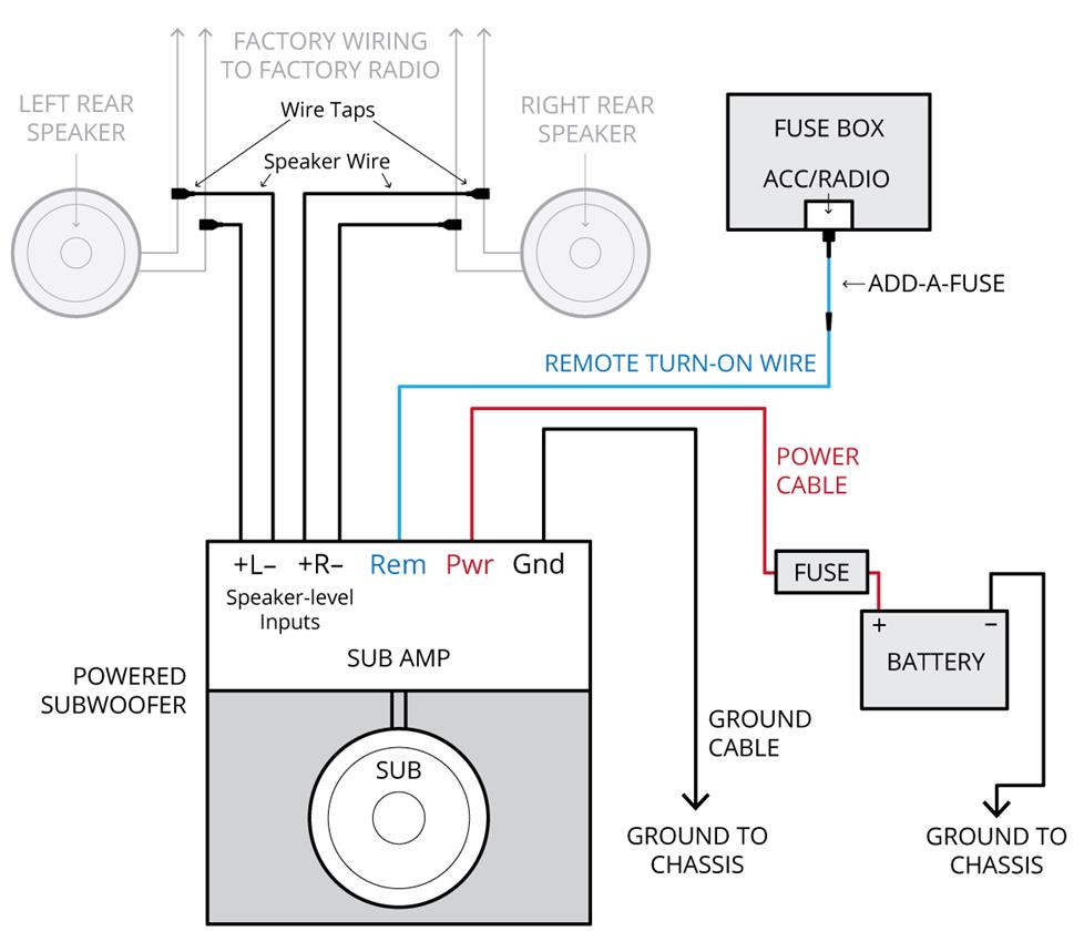
Learn how to wire your sub and amp with our subwoofer wiring diagrams. At this time we are delighted to declare we have discovered an.

6 Channel Amp Wiring Diagram Wiring Library

Can i just add the wires to the.

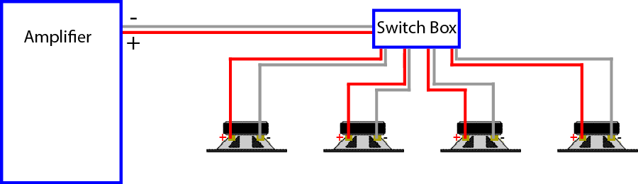
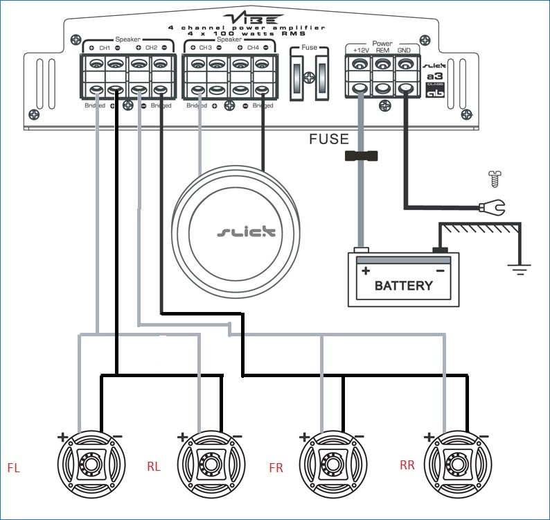
6 speakers 4 channel amp wiring diagram. Wiring a 2 or 4 channel amp to your stock speaker harness without cutting the factory wiring. 1105 wire a 4 channel system now adding rear speakers. I have a 4 channel amp that currently runs 4 65 speakers in my boat.

How to install a 4 channel amplifier. 6 speakers need 6 channel amp. So its important to have a wiring diagram handy and to.

Here you are at our website contentabove 6 speakers 4 channel amp wiring diagram published by admin. 6 speakers 4 channel amp wiring diagram with this post we hope to give you inspiration to make wiring diagram. Learn how to properly connect your car subwoofer and amplifiers the first time.

This is just a generic type of diagram and you should consult the wiring diagram which was supplied with. I have 2 kicker 35 15watt speakers in the. 4 channel amp 6 speakers so i have a kicker 4 channel amp and i have each channel on that going to each door speaker.

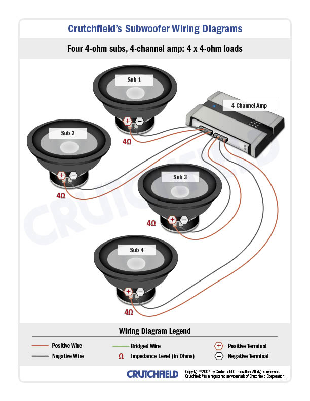
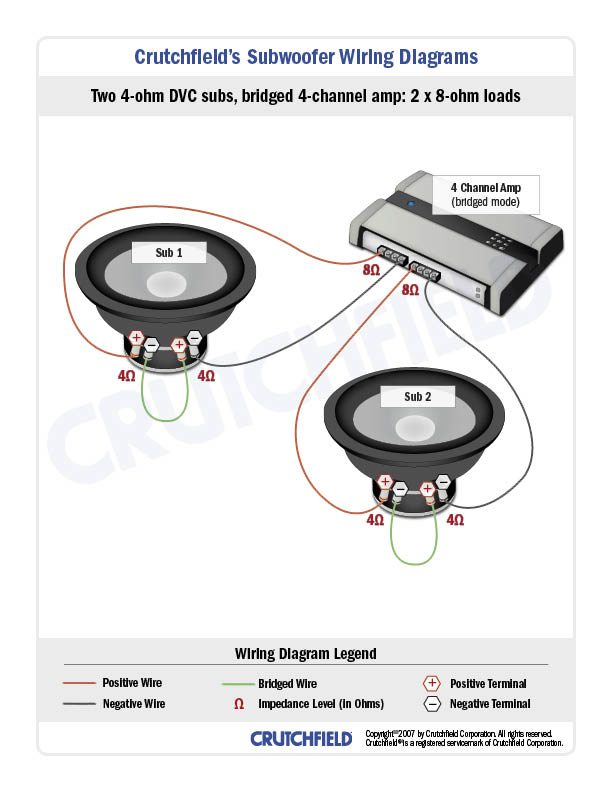
4 channel amp on front speakers 2 channel amp on subs. Be sure you wire the correct speakers to the proper channel. Wiring two 4 ohm speakers in series will result in an impedance of eight ohms.

Wiring speakers to your marine amplifier. The hull truth boating and fishing forum. For useful information about marine stereo systems watch this video.

I want to add two and maybe even 4 additional 65 speakers.

6 Channel Amp Wiring Diagram Wiring Library

Mono Amp 2 Speaker Wiring Diagram Wiring Diagram Detailed

Speaker Amp Wiring Diagram Wiring Library

6 Channel Amp Wiring Diagram Wiring Library

6 Speaker Wiring Diagram Change Your Idea With Wiring Diagram Design

Stereo Earphone With Multiple Speakers On Wiring Multiple Car

Bridge Speakers Wiring Diagram Wiring Diagram Detailed

Car Amp Wiring Diagram 4 Way Data Wiring Diagram

6 Channel Amp Wiring Diagram Wiring Library

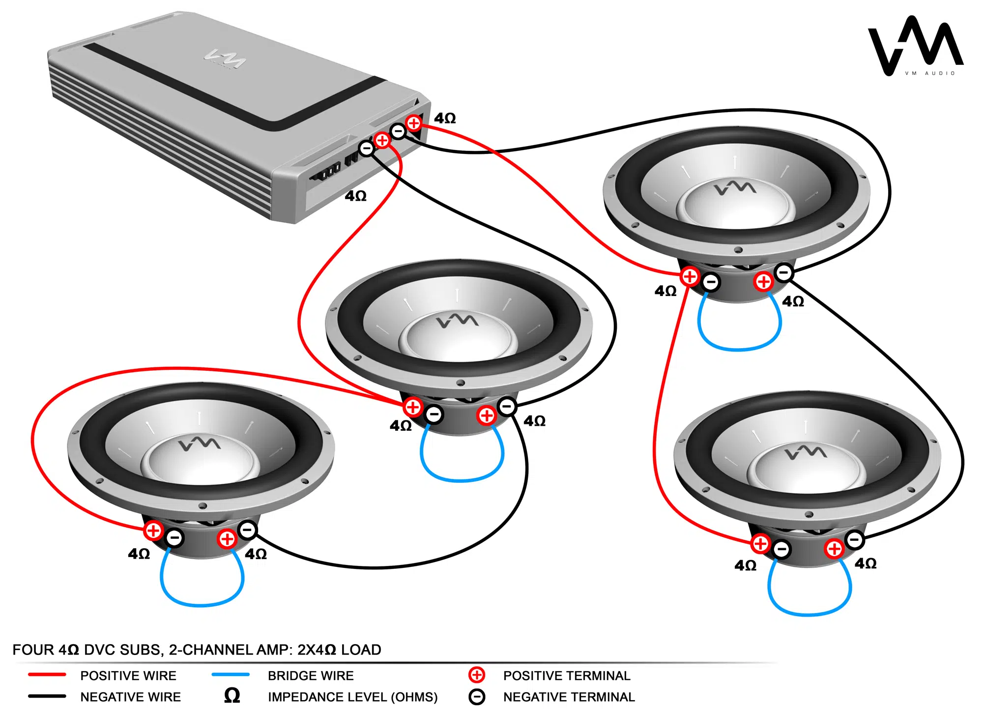
Dual Voice Coil Dvc Wiring Tutorial Jl Audio Help Center

Product Information Ca800 Car Amplifier

Wiring 4 Channel Amp 2 Speakers 1 Sub Wiring Diagrams Source

6 Channel Amp Wiring Diagram Wiring Library

Wiring 4 Channel Amp 2 Speakers 1 Sub Wiring Diagrams Source

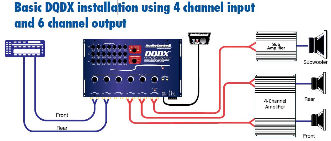
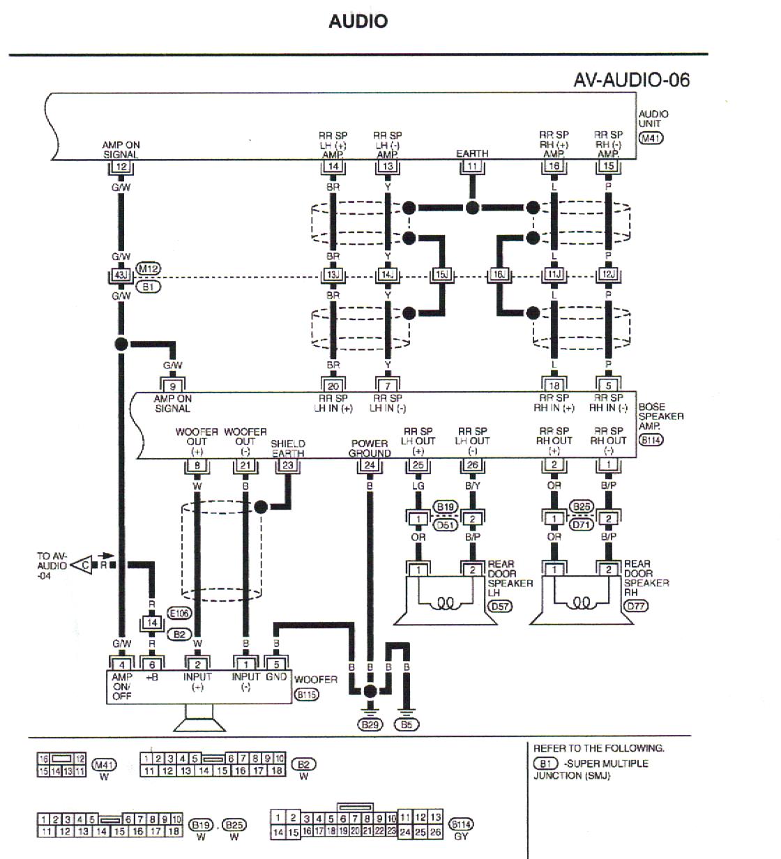
How To Replace Your Dsp Amp With An Aftermarket Unit

Wiring 4 Channel Amp 2 Speakers 1 Sub Wiring Diagrams Source

Car Amp Wiring Diagram 4 Way Data Wiring Diagram

Car Tweeter Speaker Wiring Diagram Wiring Library

Wiring 4 Channel Amp 2 Speakers 1 Sub Wiring Diagrams Source

How To Hook Up 2 Channel Car Lifiers On 2 Channel Amp Wiring Diagram

Car Amp Wiring Diagram 4 Way Data Wiring Diagram

Amplifier Wiring Diagram For A House Schema Wiring Diagram Online

Bridge Speakers Wiring Diagram Wiring Diagram Detailed

Wiring 4 Channel Amp 2 Speakers 1 Sub Wiring Diagrams Source

Car Audio Amp Wiring Diagrams Wiring Diagram Schematic Name

4 Channel Amp Speaker Wiring Diagram Wiring Library

Component Speakers 4 Channel Amp Wiring Diagram Wiring Library

Amplifier Wiring Diagram For A House Schema Wiring Diagram Online

How To Hook Up 2 Channel Car Lifiers On 2 Channel Amp Wiring Diagram

Stereo Earphone With Multiple Speakers On Wiring Multiple Car

Wiring 4 Channel Amp 2 Speakers 1 Sub Wiring Diagrams Source

Loudspeaker Wiring Diagrams Wiring Diagram Schematic Name

Power Amp Wiring Diagram Wiring Diagram Detailed

6 Channel Amp Wiring Wiring Diagram Library

6 Speakers 4 Channel Amp Wiring Diagram Gallery Wiring Diagram Sample

6 Speakers 4 Channel Amp Wiring Diagram Free Wiring Diagram

6 Speakers 4 Channel Amp Wiring Diagram Fresh Car Stereo Wiring

70 Volt Volume Control Wiring Diagram Lovely 6 Speakers 4 Channel

6 Speakers 4 Channel Amp Wiring Diagram Lovely Awesome 5 Channel Amp

6 Speakers 4 Channel Amp Wiring Diagram 39 Wiring Diagram Images

5 Channel Amp Wiring Diagram Lovely 6 Speakers 4 Channel Amp Wiring

6 Speakers 4 Channel Amp Wiring Diagram Gallery Sample Ripping Sub

4 Channel Amp Speaker Wiring Diagram 6 Speakers 2 Simple Mono To Sub

Bridge 4 Channel Amp Wiring Diagram Wiring Library

2 Channel Amp 4 Speakers Wiring Diagram 6 Double Din All Kind Of

6 Subwoofer Wiring Diagram Askyourprice Me

4 Channel Amplifier Wiring Diagram Inspirational 6 Speakers 4

Kicker Speaker 6 Wire Wiring Diagram Inspirational 6 Speakers 4

6 Speakers 4 Channel Amp Wiring Diagram Unique 5 Channel Amp

2007 Mazda 6 Radio Wiring Diagram For Speaker Wellread Me

58 Inspirational Photos Of 2 Channel Amp Wiring Diagram Wiring Diagram

6 Channel Amp Wiring Diagram New 6 Speakers 4 Channel Amp Wiring

6 Channel Car Amplifier Wiring Diagram Lovely 6 Speakers 4 Channel

2 Channel Amp Wiring Diagram 6 Speakers 4 Channel Amp Wiring

6 Speaker Wiring Diagram Astonishing Solved I Need The Stereo Wiring

Speakers Wiring Diagrams Pioneer Diagram Logitech Car Stereo Speaker

6 Channel Car Amplifier Wiring Diagram Unique 5 Channel Car

6 Speakers 4 Channel Amp Wiring Diagram Great Installation Of

2 Channel Amp Kicker Wiring Diagram Not Lossing Wiring Diagram