If your NJK-5002C can source 150mA of current its safe to connect a standard electromagnetic relay solid state relay module dc buzzer or a small hooter between its black and brown leads as pointed in the above schematic. DC 10-30V NC two wire SN04-A.
Sn04 N Inductive Proximity Sensor Npn Wires No 6 36v Dc 18x18x36mm Techonics Ltd
DC 10-30V NPN NO Three wire SN05-N2.

Sn04-n wiring diagram. -easy mounting-water proof and dust proof. I recently got the SN04-N proximity sensor shown below in a Google image. 1 x Proximity Square.
DC versions 直流接線. SN04-N Inductive Proximity Sensor - 5mm ID. The blue wire can be connected to the boards old switch black wire which is a common ground.
You can use a 12V sensor adapter toWiring Diagram Symbols Pdf Diagrams Are Usually Found Where For Trailer Lights Lance Schematic Awesome Barker Electric Jack. DC 10-30V NO two wire SN04-D2. DC 3 wire PNP P DC 3 wire NPN N DC 3 wire PNPNPN K DC 2 wire 34 D DC 2 wire automobile 14 C DC analog output A AC 2 wire F ACDC 2 wire M ACDC 2 wire SCP protect S ACDC relay output R BUS B FUNCTION Analog 0.
PnP and DIY kits. -low cost stable detection. Test this with a multimeter to be sure you have the same kind of sensor I have and adjust accordingly if it is the opposite.
3528_0 Recommended for new designs. AC 220V NC two wire Size18mm18mm35mm Sensing distance4mm Size18mm18mm35mm Sensing distance. In this video I explain how I use them and how to select a pull down.
The magnetic pickup sensor is from Dart Controls. The black wire will output 12V when the sensor is far from any metal and 0V when it is close to a metallic object. I have a ROKO Sn04-SNN.
10mA 1 Analog 420mA 2 NO. Sn04 n proximity sensor wiring diagram. 22 Wiring The 3DTouch Auto Leveling sensor has 5 wires 3 for the first servo connection and 5v and 2 for the Z min end stop negative and signal pins.
Wiring Diagram Schematics Best Place to Find Wiring and Datasheet Resources. April 12th 2019 - Side Plug Truck Wiring Diagram 7 2016 Ford F150 Trailer Wiring Harness Audi A4 Tailight Wiring Sn04 N Proximity Sensor Wiring Diagram Ideal Cat 5 Wiring Diagram 08 Ram Stereo Wiring Diagram Leviton 3 Way Switch Wiring Diagram Carrier Wiring Diagrams Pdf Badland Winch Wireless Remote Box Diagram 2007 Harley. Wiring diagrams 接線圖.
Heres the basic wiring diagram for practical applications of the NJK-5002C sensor. With Connector for Anet. Circuit Operation If its a PNP transistor the base is coupled at the collector of the photo transistor alternatively if a NPN transistor is used in the relay driver the trigger is received from the emitter of the photo transistor quite like a Darlington paired configuration.
C Programmablewiring P Programmable S CABLING OR CONNECTION M8X1 Nano S M. DC 3-wire NPN NC Theory. 6-38 V5 V no.
DC 10-30V PNP NO Three wire. The trick is figuring out which wires make up the coil pairs. NPN Switched Negative Switched refers to which side of the controlled load relay small indicator PLC input is being switched electrically.
Inductive NPN Proximity Switches are easy to use as limit switch for hobby CNC machines. Wiring an autoleveling sensor. Heres a simple way remember how to wire up a 3-wire DC PNP or NPN sensor.
The brown wire goes directly to the power supply 12V. Connecting 4-wire stepper motors requires connecting A and A- to one of the motor coils and B and B- to the other motor coil. 8 C 60 8 C.
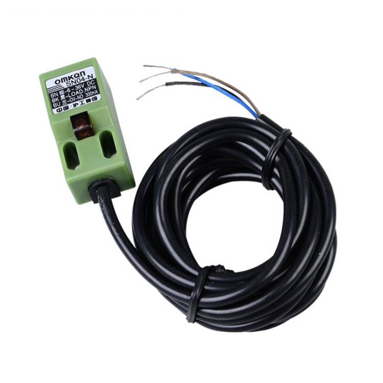
Inductive Proximity SensorSN04-NNPN3-wire NO6-36V DC 181836mm Wiring Diagram. Here is a link for the specificationshttpwwwdartc. The comes with ferrules crimped onto the wires to ensure a good connection when used with screw terminals.
3DTouch can be operated in the following condition. We will show the wiring of an NPN sensor into a PLC. 10-30 V5 V no.
I have a 3-pin JST XH connector to solder these into to connect into the Z- slot or Z maybe if my firmware is configured that way but I dont know the order that these wires should be oriented on. The official Anet sensor. The second pic is showing how i wired it the pic is just from google which i only post to show ppl how to wire it the ground needs to be shared between the s_z port ground and the negative where the positive brown wire is going i just use the leads coming from my power supply to the heated bed power expansion module and i can take a pic of my set up on how i did it if anyone is interested or has.
Is not the original manufacturer for this product but we intend to sell it or a similar replacement with a compatible form fit and function for as long as it is available from the supplier. AC 220V NO two wire SN04-A2. 6-36 V5 V no.
DC 3 Wire Type Black Brown Blue. These cables are color coded such that the A wire is red the A- wire is black the B wire is yellow and the B- wire is purple. As shown in the following circuit diagram the relay driver may consist a NPN transistor or a PNP transistor.
One IO for control PWM or Software PWM One IO for Z min Z Probe GND and 5V power. PNP Switched Positive. DC 10-30V NPN NC Three wire SN05-P.
36 x 18 x 18cm 14 x 07 x 07 LWH.


