Input voltage for the DC coil. Relay TerminalsQuick Connect RoHS Compliant.

Wiring Diagram For 220 Volt Submersible Pump Http Bookingritzcarlton Info Wiring Diagram For 220 Volt Subme Submersible Well Pump Well Pump Submersible Pump
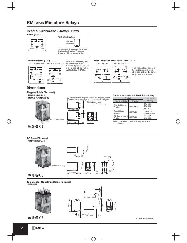
The RR Series has a 10A contact rating.
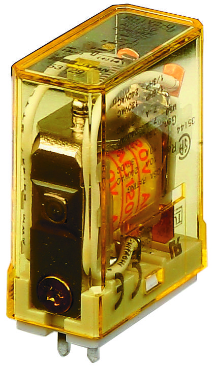
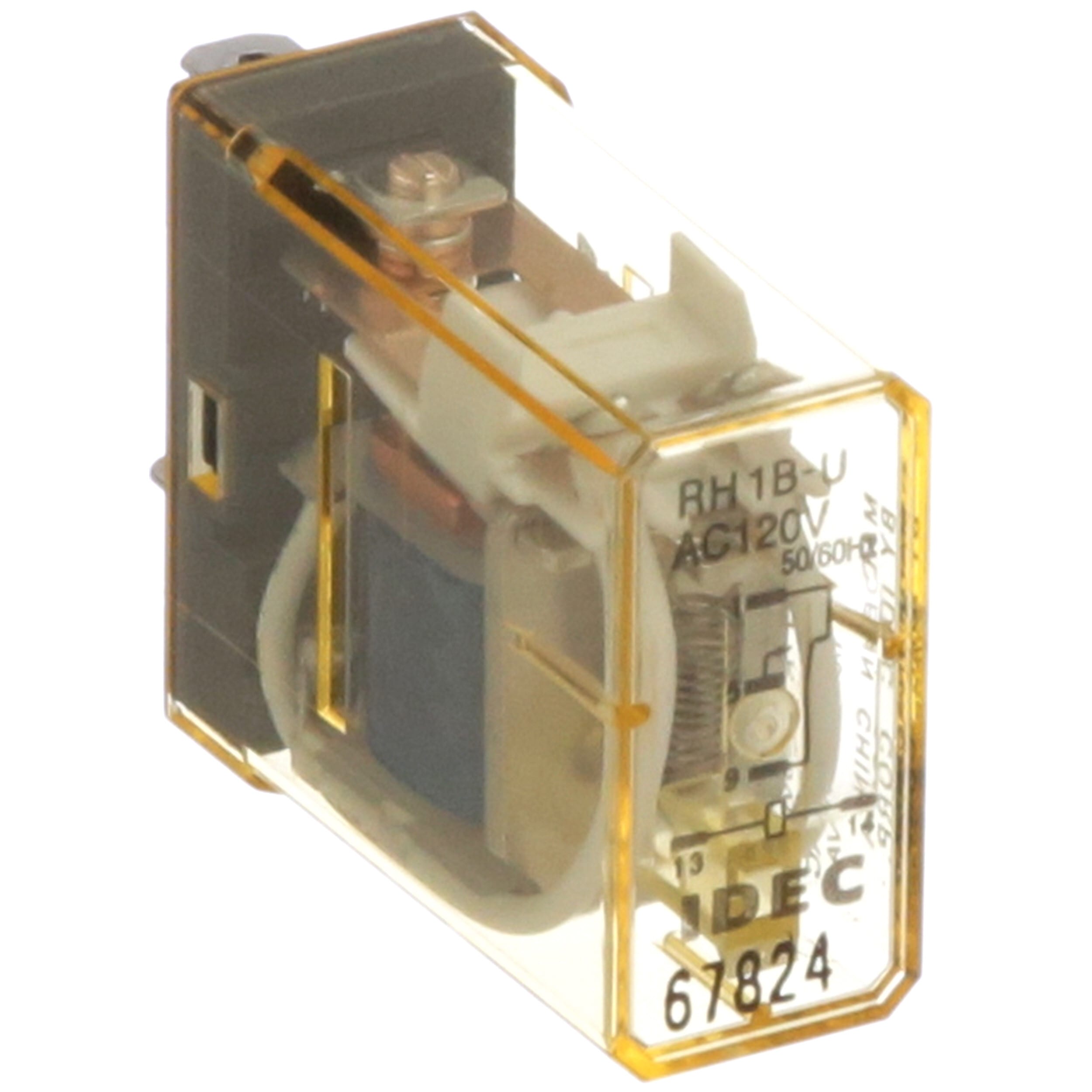
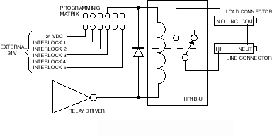
Rh1b-u wiring diagram. This RH-series power relay has SPDT AgCdO contact with indicator. 125S Wiring Diagram The electrical system consists of battery CDI unit carburetor heater sidestand switch horn rectifier regulator ignition coil rear brake light switch starter relay etc Service Manual SYSTEM WIRING DIAGRAMS Print Date 10 8 April 6th 2019 - diagram 3 of 8 air conditioning amp cooling fans systems air. 181 rows IDEC Corporation.
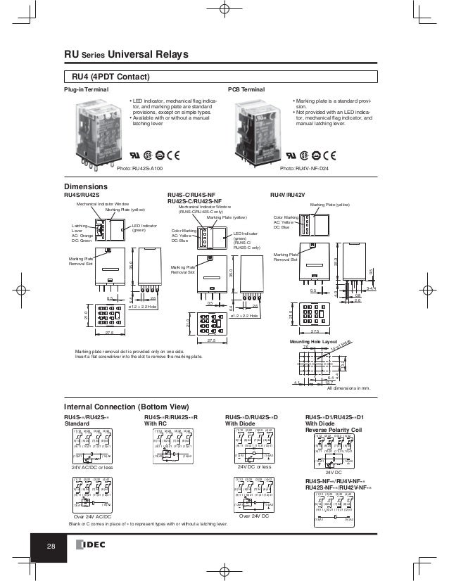
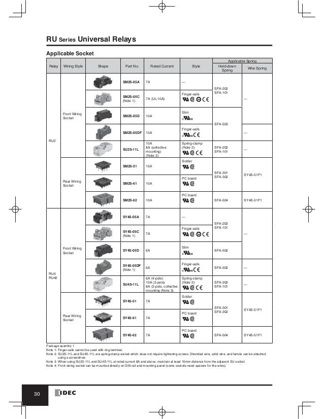
The RR Series relays are available in SPDT DPDT and 3PDT configurations driven by AC or DC coils and they have pin or blade terminals for socket mounting. Electrical Life Curves RU2 Resistive Load RU4 Resistive Load. Now that we know what each terminal pin represents we now wire it to a circuit for it to do a real-world function.
It shows the components of the circuit as simplified shapes and the talent and signal links amongst the devices. Options include manual check buttons LED indicators and top flange covers for direct surface mounting. Rh1b U Wiring Diagram wiring diagram is a simplified okay pictorial representation of an electrical circuit.
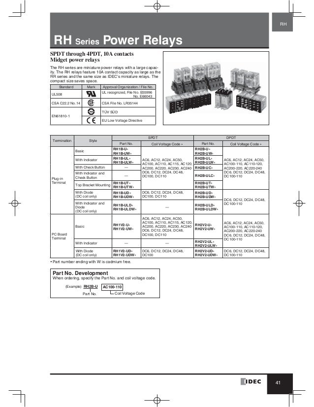
Miniature power relay with a large capacity. IDEC SH1B-05 10 AMP Relay Socket DIN-Rail Screw TERMINALS 300 VAC 567. Sockets Terminal Electrical Rating Wire Size Torque DIN Rail Mount Sockets SH1B-05 Coil M3 screws contact M35 screws with captive wire clamp 250V 10A Maximum up to 212AWG 55 - 9 inlbs 9 - 115 inlbs SH2B-05 SH3B-05 SH4B-05 M35 screws with captive wire clamp 300V 10A Maximum up to 212AWG 9 - 115 inlbs Finger-safe DIN Rail Mount.
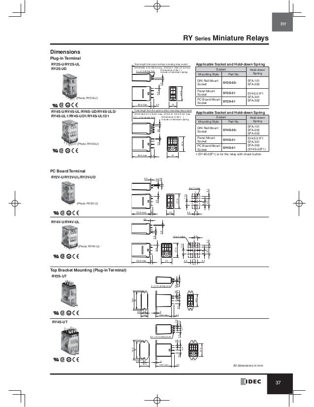
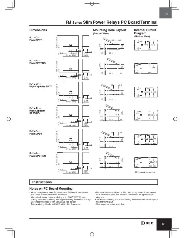
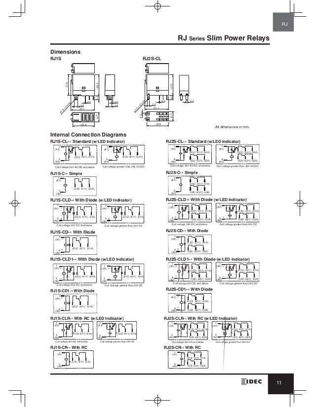
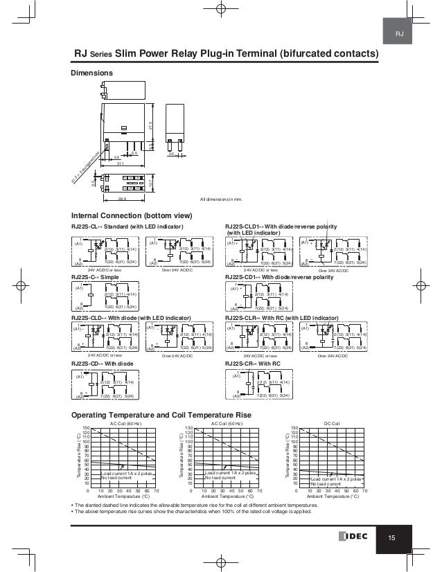
The RJ Series is compact to reduce space requirements. 2 pieces included with each socket. For use on DIN rail mount socket when using pullover wire hold down spring.
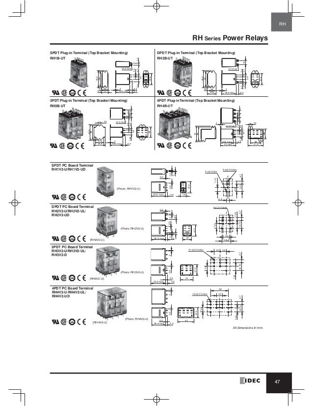
Available in 1 to 4 poles with either 187 blade plug-in or PCB terminals the RH series is known for going the distance. NEMA A1 A2 IEC NEMA Wiring Diagram IEC Bottom View 114 Flag indicator Removable ID. UL Ratings Voltage Resistive General Use Horse Power Rating RH1 RH2 RH3 RH4 RH2 RH3 RH4 RH2 RH3 RH4 240V AC 10A 75A 75A 7A 65A 5A 13 HP 13 HP 120V AC 10A 10A 75A 75A 16 HP 16 HP 30V DC 10A 10A 7A.
Tag Contact options for different power levels UL 508 Units Fine Silver Gold Diffused Resistive 3A 120V 5060Hz Resistive 3A 240V 5060Hz Resistive HP 110 120VAC HP 110 240 VAC Pilot Duty mA 3. Driving Circuit for Relays. The RH1B-ULDC24V is a general-purpose Compact Power Relay with DC coil.
RH1B-UAC120 RELAY SPDT 110VAC 30VDC 10A. Highly resistant to inrush with a built-in snubber the RSS series is ideal for switching loads such as lights and heaters. Rh2b-u wiring diagram ups 500va 220v 50hz circuit diagram transformer 220V to 30v 500w 6v 511 spdt relay series 511 spdt relay 12v dc RJ2S-CL-D24 relay idec sy4s-05 14 pin wiring diagram relay 6v dc 10amp RY2S-U Text.
IDEC rr2p-u wiring diagram. The hockey puck style RSS series of solid state relays allow switching of the most demanding loads. Buy the items featured in this video at 800-337-1720 or visit.
Sockets Terminal Electrical Rating Wire Size Torque DIN Rail Mount Sockets SH1B-05 Coil M3 screws contact M35 screws with captive wire clamp 250V 10A Maximum up to 212AWG 55 - 9 inlbs 9 - 115 inlbs SH2B-05 SH3B-05 SH4B-05 M35 screws with captive wire clamp 300V 10A Maximum up to 212AWG 9 - 115 inlbs Finger-safe DIN Rail Mount. Want to support the channel. Wiring layout Section F.
Ships from and sold by Ralphs Industrial Electronic Supplies. IDEC RY-Series General Purpose Relays presented by Katie Rydzewski for Galco TV. Were going to connect a single pole double throw relay to a circuit to light up a LED.
Using a standard terminal arrangement the RH. How a relay works in easy to understand language. Electrical Life Curves 13 5 7 92468 10 50 20 10 100 500 1000 AC 110V Resistive AC 220V Inductive AC 220V ResistiveAC 110V Inductive Load Current A Life x 10000 Operations 1 2468 103579 50 20 10 100 500 1000 DC 30V Resistive DC 30V Inductive DC 100V Resistive AC 220V Resistive DC 100V Inductive Load Current A 13 5 7 92468 10 50 20 10 100 500.
They are available in a 12A SPDT version and an 8A DPDT version. All models carry worldwide approvals including UL CSA TUV and CE. Idec Relay Wiring Diagram Start Building A Wiring Diagram Rh2b U Relay Wiring Diagram Detailed Schematics Diagram Rh Lelandlutheran Com 8 Pin Relay.
When the relay is powered the red LED shuts off and the green LED lights up. A wiring diagram is often used to troubleshoot problems and to create distinct that all the associates have been made and that anything is present. A pictorial diagram would undertaking more detail of the physical appearance whereas a wiring diagram uses a more symbolic notation to bring out interconnections exceeding mammal appearance.
Available with either DC 4-32V or AC 90. When the relay isnt powered the red LED is lit and stays on. Wiring layout Section F.
Blade terminal with solderplug-in type mounting compact size saves space. IDEC RH1B-U-AC120V Relay 5 Blade 120 VAC Coil SPDT 10 AMP Plug-in 1200.
Catalog Relay Idec Www Haophuong Com

Flojet Question Page 2 Car Wash Forum
Catalog Relay Idec Www Haophuong Com
Catalog Relay Idec Www Haophuong Com
Catalog Relay Idec Beeteco Com
Catalog Relay Idec Www Haophuong Com
Catalog Relay Idec Www Haophuong Com
Idec Corporation Rh1b Uac120v Relay 120 Vac Power 8100 Ohms 35 6 Mm H X 14 Mm W X 27 5 Mm D 30 Min Allied Electronics Automation
Catalog Relay Idec 2019
Catalog Relay Idec 2019
Catalog Relay Idec 2019

Fujitsu Ten Limited Wiring Diagram In 2021 Electrical Wiring Diagram Electrical Diagram Trailer Wiring Diagram
Rh1b Uac120v Idec Power Relay Spdt 120 Vac
Catalog Relay Idec Www Haophuong Com
Sa Idec Izumi Genuine And Spring Relay Rh1b U Dc24v Relay Dc 24v 5 Feet 10pcs Lot Relay Dc Dc Relay24v Dc Relay Aliexpress

Hilux Electrical Wiring Diagram

Mf 35 Wiring Diagram Dat Wiring Diagrams In 2021 Electrical Wiring Diagram Diagram Massey Ferguson
8 Channel Relay Module With Rh1b U Relays Model 2650

Catalog Relay Idec Www Haophuong Com


