What Are Series And Parallel Circuits Electronics Textbook. 14 Parallel Circuit Drawing.

140w Power Amplifier Circuit Tip3055 Tip2955 Power Amplifiers Circuit Diagram Circuit
Measure the current strength using the ammeter.

Schematic circuit diagram for both parallel and series circuit. Series And Parallel Circuit Diagram - Series And Parallel Dc Circuits Explained Examples Included Electrical4u A complex circuit can consist of sub circuits of each a simple schematic of a parallel circuit is shown below. In the below circuit diagram there are three capacitors connected in parallel. Most electronic circuits fall into this category.
Parallel Series Circuit Diagrams. These paths are called branches. Bosch series parallel switch wiring diagram.
SERIES VS PARALLEL CHART Series Parallel Voltage V Vtot V1 V2 V3. Given two cylinders in a parallel relationship with the following dimensions calculate the extension sequence if the cylinders are both loaded with 800lbf loads. Series and parallel circuits diagram wiring schematics in to build leds correctly 3 645 best circuit images simple resources.
Parallel series circuit diagrams posted by margaret byrd posted on october 15 2017. In general we may have unequal resistances R_1 and R_2 as in c1. SCHEMATIC DIAGRAM REPRESENTATION Schematic Pictorial series 7.
Apply KCL at node A. Series-parallel circuits are typically used when different voltage and current values are required from the same voltage source. Page 2 of 18.
Remove the ammeter and close the circuit. Circuit Diagram For Series And Parallel. C T C 1 C 2 C 3 Where C 1 47uf.
E Total E 1 E 2. - The charge divides into multiple pathways passing through only one of the branches. Lets explore and see whats ahead.
Since there are only two constant-voltage areas in the circuit c2 all three components have the same voltage difference across them. R Total 1 1R 1 1R 2. Overview of Series-Parallel Circuits A series-parallel circuit or combination circuit combines both series and parallel connections.
Calculate the extension pressure necessary to move B. As these capacitors are connected in parallel the equivalent or total capacitance will be equal to the sum of the individual capacitance. Series Circuits Defined Two components are in series if they share a common node and if thes ame current flows through.
Series parallel combination circuits and dc simple learn 3 644 best circuit images resources examples to build. Parallel Circuit - Voltage A charge only passes through a single resistor. One of the simplest examples to analyze is the parallel resistance circuit of which figure b was an example.
Combine the series resistors and then the parallel resistors on the right branch. What Is A Series Parallel Circuit Combination Circuits Electronics Textbook. The basic schematic circuit layout of a 1224 volt series parallel switch.
The two simplest of these are called series and parallel and occur frequently. When a circuit is modeled on a schematic these nodes represent the wires between components. Set up a parallel circuit with two cells in series with each other and three torch light bulbs in parallel with each other.
Series And Parallel Circuits. 2 offices make use of parallel circuits to power the appliance but series circuits control the power. I Total I 1 I 2.
A travel 6 B cap 2 B rod 58. Insert an ammeter in series between the cells and the first pathway as shown in the diagram. Thats the key difference between series and parallel.
A battery normally succeeds in maintaining the voltage differences across. C 2 1uf and C 3 01uf So C T 47 1 01uf C T 58uf. Equivalent circuit - Combining series and parallel circuits Labelled nodes are on the previous diagram.
Voltage drop across the resistor that it chooses to pass through must equal the voltage of the battery. Calculate the extension pressure necessary to move A. Total resistance in a parallel circuit is less than any of the individual resistances.
1R n Total current in a parallel circuit is equal to the sum of the individual branch currents. PARALLEL CIRCUIT - A parallel circuit has two or more paths for current to flow through. Components in a parallel circuit share the same voltage.
Posted by Margaret Byrd Posted on November 20 2020. - Voltage is the same across each branchcomponent of the parallel circuit. 2 The new circuit is B A C Figure 7.
Example for Parallel Capacitor Circuit. The set of two 2 ohm resistors will combine to 4 ohms because they are in series. B travel 6.
Total voltage the voltage across each individual resistor VT V1 V2. A cap 1 34 A rod 58. Posted by Margaret Byrd Posted on October 15 2017.
Series components form a series.

This Is The Schematic Diagram Of 35w Bridge Power Amplifier Circuit Delivers 35w Power Output For 8 Speaker T Circuit Diagram Power Amplifiers Speaker Plans

A Large Online Repository Or Library Of Guitar Pedal Schematics Layouts Pcb Transfers And Tagboar Electronic Circuit Design Circuit Diagram Diy Guitar Pedal

Aquarium Temperature Probe Probe Electronics Circuit Diagram Electronic Schematics

This Editable 4 Page Worksheet Provides Practice For Drawing Series And Parallel Circui Science Lessons Elementary Teaching Scientific Method Literal Equations

Pin On Electrical Circuits

Pictorial Diagram Diagram Circuit Diagram Electrical Diagram

Schematic Diagram Electricity Electrical Engineering Diagram

Pin On Back To School

140w Power Amplifier Circuit Tip3055 Tip2955 Circuit Diagram Power Amplifiers Circuit

Symbols Lovely Samsung Power Supply Schematic Circuit Diagram Untitled Of A Variable 12v Dc Simple Regulat Electrical Circuit Diagram Circuit Diagram Diagram

Series And Parallel Circuits On White Background Helpful For Basic Education Series And Parallel Circuits Parallel Circuit Circuit

Pin On Electronic

This Solid State Ac Relay Switch Circuit Is Useful In Ac Switching Without Mechanical Relay In This Solid State Re Circuit Diagram Circuit Electronics Circuit
Pin On Basic Electronics

An Schematic Diagram Is A Simplified Conventional Graphical Representation Of An Electrical Circuit We Series Parallel Series And Parallel Circuits Dc Circuit
Inverter Circuit Diagram Inverter 12 Volt Dc To 220 Volt Ac With Output Current 2 Ampere Circuit Diagram Circuit Electronics Circuit

Pin On Audio

Circuit Diagram Automatic Headlight Schematic Board Simple Schematic Collection Headlightautomaticswitchcircu Circuit Diagram Diagram Electronic Schematics

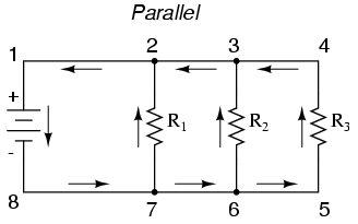
Schematic Three Resistors In Parallel Circuit Drawing Parallel Circuit Series And Parallel Circuits


