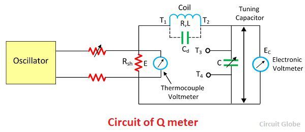
Figure 2 - Q Meter Circuit Diagram. The output of the oscillator is shorted by a low-value resistance Rsh usually of the order of 002 ohm.

Simplified Diagram For The Q Meter Series Resonant Measuring Circuit Download Scientific Diagram
Q-meter circuit connections are done as shown in diagram.

Q meter circuit diagram. Figure 1 Block diagram of the classical Q meter as used in the HP 4342A. If it is very much below the specified 200 volts set your test meter to AC. The ratio of the inductive reactance to the effective resistance of the coil is called the quality factor or Q-factor of the coil.
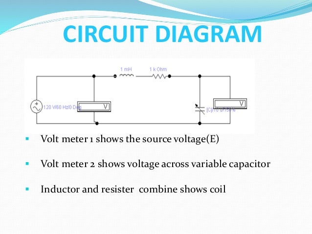
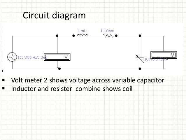
Set the voltage value of the oscillator E10 V. In this circuit we have resistor inductor and capacitor which are connected with the AC source in series. An interior view of the Q Meter.
Circuit Diagram for Q meter experiment Set the Shunt Resistance R sh value as small as possible Say 002 Ohm. If the voltage applied across the circuit is kept constant then voltmeter connected across the capacitor can be calibrated to indicate Q directly. Schematic Diagram of Heath QM-1 Q Meter.
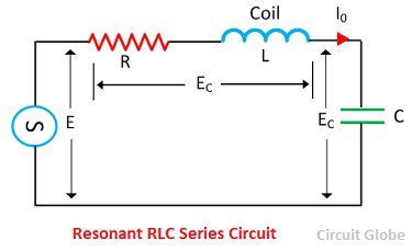
R13 02 Ω is five 1 Ω composition resistors in parallel. We know that every inductor coil has a certain amount of resistance and the coil should have lowest possible resistance. The voltage across the resistor and inductor is collectively represented by E L and the voltage across the capacitor is represented by E c an the current flowing in the circuit is I o.
Check the value of voltage drop across capacitor. Set all the parameters R L C by yourself. The value of the shunt resistance may be typically 02 Ω.
This resistor introduces almost no resistance to the series RLC circuit and makes the. The output of the oscillator is shorted by a low-value resistance Rsh usually of the order of 002 ohm. The resonance is the condition exists in the circuit when their inductance and capacitance reactance are of equal magnitude.
Printed circuit TRACK PATTERN in Encapsulated Postscript format eps for. It consists of an oscillator which works in the frequency range of 50 kHz to 50 MHz. Measure the voltage at the cathode pin 6 of V5.
Circuit diagram of the direct connection of Q-meter is shown below. A wide range oscillator with frequency range from 50kHz to 50 MHz is used as a power supply to the circuit. The circuit uses a wide range radio frequency oscillator having frequency range from 50kHz to 50MHz as the voltage supply source.
Make sure the heater in V5 6X5 is lighting up orange. Circuit diagram of a Q-meter is shown is figure. Variable calibrated capacitor Variable frequency ac voltage source Coil to be tested or measured All elements are connected in series.
A wide-range oscillator with frequency range from 50 kHz to 50 MHz is used as a power supply to the circuit. The figure below shows a coil of resistance inductance and capacitance connected in series with the circuit. The Q-meter is based on the characteristic of the resistance inductance and capacitance of the resonant series circuit.
One terminal of the coil is connected to the signal generator Ac voltage source while the other terminal is connected to the variable capacitor. A JPEG picture file showing mechanical details of the daughterboard. Circuit diagram of the direct connection of Q-meter is shown below.
Printed circuit TRACK PATTERN for Autotrax PCB viewed from bottom A JPEG picture giving drilling details for the PCB groundplane. Q Meter Circuit The circuit diagram of the Q meter is shown below. A wide range oscillator with frequency range from 50kHz to 50 MHz is used as a power supply to the circuit.
To Calibrate set Sig Gen level for half scale on M1. Q - meter circuit diagram A wide range of oscillator with frequency range from 50 kHz to 50 MHz is used as a power supply to the circuit. The capacitor voltage Vc and the source voltage E are monitored by voltmeters.
The output of the oscillator is shorted by a low value resistance R sh usually of the order of 002 ohm. And provides current to a shunt resistance Rshwith 002 ohms value. If you need to troubleshoot your Heath Q meter here is a schematic diagram.
Circuit diagram of a Q-Meter. CONSTRUCTION Q meter consist of the following major elements. The oscillator drives a current through a low value of resistance R sh.
They induce energy which is oscillating between the electric and magnetic field of the capacitor and inductor respectively. So Q XL R ωL R. A wide-range oscillator with frequency range from 50 kHz to 50 MHz is used as a power supply to the circuit.
It is designed with an oscillator that uses the frequency that ranges from 50 kHz 50 MHz. For a verbal description click here. The oscillator terminals are shorted by a resistor of the order of 002Ω.
The output of the oscillator is shorted by a low-value resistance Rsh usually of the order of 002 ohm. Figure 2 The signal generator and the source are weakly coupled to the L-C circuit under. Test terminals 1-4 are to connect Lx and Cx.
The block schematic diagram of a Q meter is shown in Figure. The front view of the Q Meter. The circuit through which we can understand the working of the Q meter is.

Q Meter Circuit Diagram Working Principle Impedance Measurement

Novel Q Meter Edn
What Is Q Meter Definition Working Principle Applications Circuit Globe

Pin On Rangkaian Elektronik

Q Meter Electrical Simple
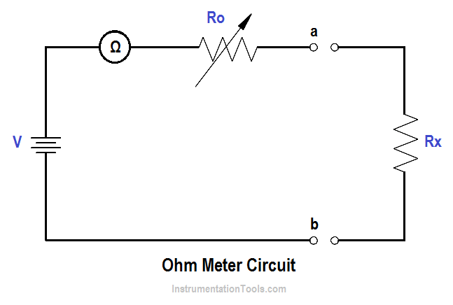
Ohm Meter Inst Tools

Q Meter Circuit Diagram Working Principle Impedance Measurement
Q Meter Ppt
Q Meter Rlc Meter

File Q Meter Circuit Png Wikimedia Commons

Schematic Diagram Of The Q Meter Operating At 300 Mhz Q 1 Q 2 Download Scientific Diagram

Q Meter Block Diagram

Q Meter Block Diagram And Working Electronics And Communication Study Materials

Q Meter Basics How To Design Q Meter Circuit
What Is Q Meter Definition Working Principle Applications Circuit Globe

Led Chaser Circuit With Pcb Layout Running Lights Eleccircuit Com Circuit Led Electrical Circuit Diagram

Voltmeter Ammeter Wiring Diagram Function Generator Volt Ampere Fm Transmitters

Simplified Diagram For The Q Meter Series Resonant Measuring Circuit Download Scientific Diagram

Q Meter Working Applications Electricalvoice


