Check the accuracy of the circuits construction following each wire to each connection point and verifying these elements one-by-one on the diagram. Block - diagram on Pic is a simplified schematic of an AM transmitter.

Sansui Tv Circuit Diagram Free Download Circuit Diagram Images Circuit Diagram Circuit Board Design Crt Tv
Carefully build this circuit on a breadboard or other convenient medium.
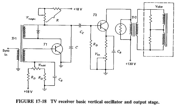
Illustrate the schematic diagram of tv vertical stage. It resemble a ladder which is why it is named ladder diagram. It provides a path for current to flow through the flybacks primary winding and horizontal yoke as shown in Figure 2. Next in the supply chain is manufacturing.
In reality there are some additional stages in professional transmitters that provide the necessary work stability transmitter power supply cooling for certain stages etc. The instruction sequence is shown vertically from top to bottom. Figure 62 Schematic diagram.
Stage 1 injection followed by stage 2 holding pressure and plasticating and finally stage 3 ejection of the moulded part. If you are troubleshooting your LED LCD or Plasma TV to find out what the issue is these repair and service. Each instruction is divided into its component stages.
A pipeline diagram shows the execution of a series of instructions. There are three main stages in the injection moulding cycle. The services products and diagrams that the customer has received can be copied edited saved and used by the customer for their personal and commercial use.
Continued on page 24. Relay wiring and automatism schematic diagrams. In symbols and equations used these diagrams the red carrier wave is symbolized by c and the blue information signal is symbolized by m not i as is used by many texts since m stands for the modulating signal ie the information.
TV Service Repair Manuals Schematics and Diagrams. A schematic diagram is a picture that represents the components of a process device or other object using abstract often standardized symbols and lines. Illustrate how the unit works and electrical.
When stage 3 is completed the mould closes again and the cycle starts over again. V2 Volts Inverting input voltage. Figure 2 Basic waveforms.
Old PL509 TV sweep tubes were built to operate as switches so they perform very well in this saturated class achieving high anode efficiency. True The ____________________ diagram not only identifies the electrical components that are in the unit but also illustrates how the unit works and electrical connections that need to be made. The schematic symbol of an op-amp is shown below.
TV tubes effortlessly pumping out RF over the legal limit. These are the businesses that provide raw materials. 2 In the event that SDC C applies and the enclosure s in question is unimportant ie Ip 10 per ASCE 7 then the enclosure s is seismically exempt per ASCE 7 para.
Schematic diagram of two-stage cooling two-stage heating. Although steam power station simply involves the conversion of the heat of coal combustion into electrical energy yet it embraces many arrangements for proper working and efficiencyThe schematic diagram of steam power station is shown in the figure belowThe whole arrangement can be divided into the following stages for the sake of simplicity. The schematic ladder diagram resembles a ladder in that it is made up of two vertical lines representing the incoming electrical sources.
Lighting power and earth protection schematic diagrams. The left vertical line represents power rail voltage source while the right vertical line represents the ground or neutral. Supply chains consist of all the steps involved in getting a product from a raw material into the hands of the customer.
Draw the schematic diagram for the relay circuit to be analyzed. We show five stages for every instruction which will make the control unit easier. Typically the supply chain begins with the vendors or suppliers.
Simplified horizontal output stage. The production function is a short-run production function because it illustrates what happens to output as more and more units of the variable input labour are added to the fixed stock of capital. Steam Power Plant Schematic Diagram.
V0 Volts Output voltage. The diagrams in the categories below are produced under the responsibility of the ST Division Electrical Engineering and Telecom group STEL. Ladder diagram are electrical diagrams that represents an electrical circuits in industries to document control logic systems.
Clock cycles are shown horizontally from left to right. There are two vertical lines. Stage 1- INJECTION OF THE PLASTIC MELTS INTO THE MOULD.
LHC main ring magnets cabling. DelmarCengage Learning Schematic Diagram Design Schematic diagrams resemble a ladder Two vertical lines represent incoming electrical sources Electrical source. V1 Volts Non-inverting input voltage.
Electrical energy supplied. Refer to the block diagram of Figure 1. The scale of the vertical voltage axis in the time domain differs from voltage scale in the frequency.
The HOT is switched on and off by a signal applied to the base. Symbol of Operational Amplifier Op-Amp The above shown symbol is the most widely used op-amp symbol for all electronic circuits. 1 Hilti KB-TZ2 may be directly substituted for TZ in this detail.
The customer is prohibited from providing the service products and diagrams on professional download levels in the area of audio video and software transmission. High and low voltage distribution schematic diagrams. Plays in the operation of the output stage.
Output Transistor The horizontal output transistor HOT is a switch. Schematic diagrams only depict the significant components of a system though some details in the diagram may also be exaggerated or introduced to facilitate the understanding of the system. 132 is a graphic representation of equation 2 which is the short-run production function for radios.
TV Service and Repair Manuals for Samsung LG Toshiba Vizio Emerson Philips Sony Hitachi Sanyo JVC Insignia Sharp Hisense TCL Panasonic Sceptre Element TVs and more. Figure 1 Amplifier block diagram.
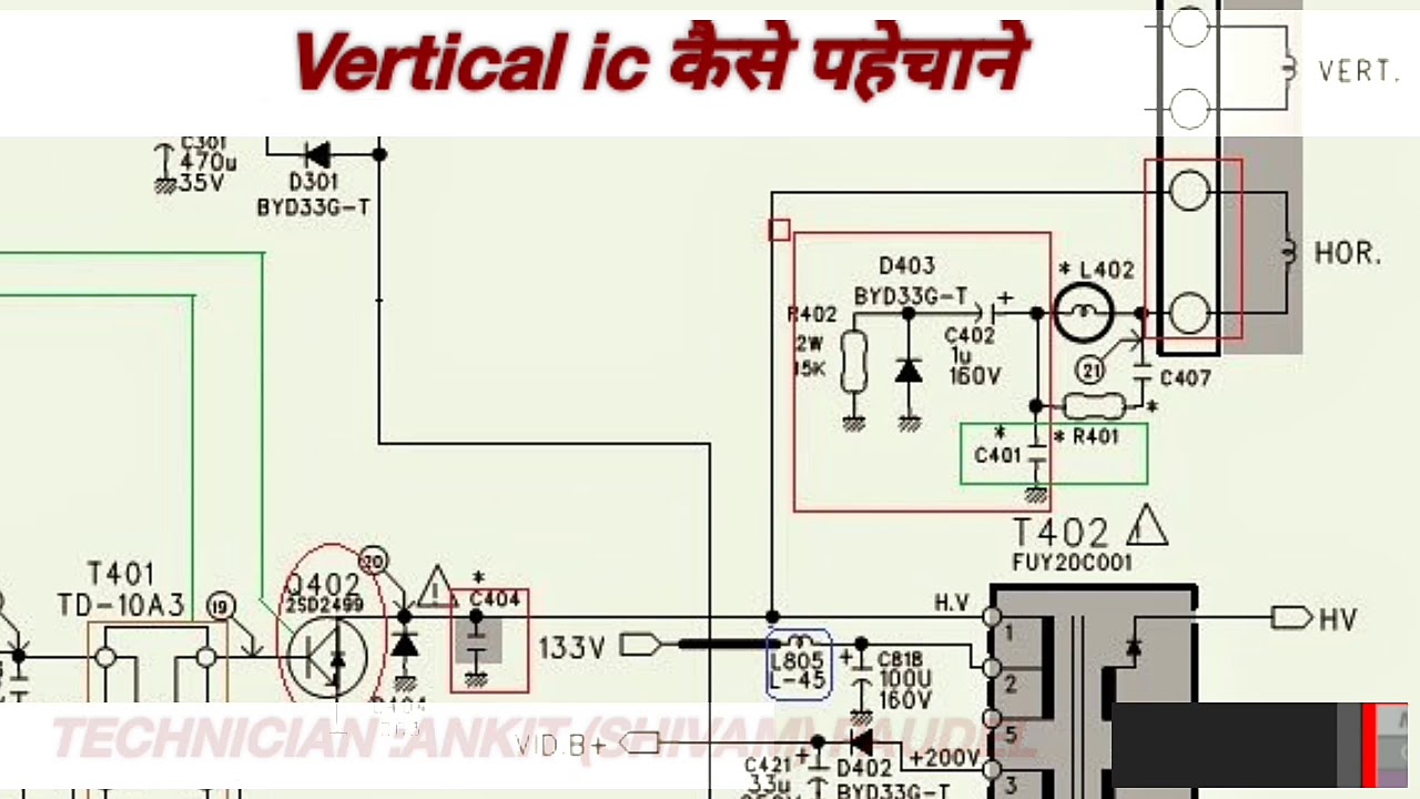
Crt Tv Vertical Ic Identify Youtube

Pin On مدارات الکترونیکی

Block Flow And Single Line Diagrams

Vertical Amplifier Block Diagram Of A Vertical Amplifier Advantages Applications

Block Flow And Single Line Diagrams

Satellite Tv System Block Diagram Download Scientific Diagram
![]()
Simple Tv Transmitter Circuit

Monochrome Tv Receiver

Electronics Idea Tda4863aj Colour Tv Vertical Ic Data Sheet
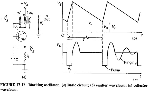
Vertical Deflection Circuit In Tv Sawtooth Deflection Waveform
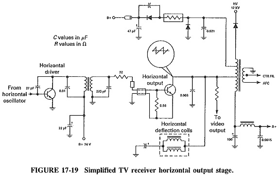
Television Horizontal Deflection Circuit Horizontal Output Stage

Electronic Repair Articles Samsung Crt Tv With H Line

Block Diagram Of A Typical L Band Satellite Tv Tuner Download Scientific Diagram

Block Diagram Of A Typical L Band Satellite Tv Tuner Download Scientific Diagram
Vertical Deflection Circuit In Tv Sawtooth Deflection Waveform
La78040 Pinout Tv Crt Display Vertical Output Ic Sanyo

Tv Receiver
![]()
Simple Tv Transmitter Circuit
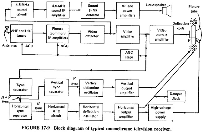
Monochrome Television Receiver Block Diagram Picture If Amplifiers


