Trace the wiring till you can see where a short may have taken place. Pt100 Rtd Sensor Pinout Features Uses Guide Datasheet.

18 Good Sample Of Window Wiring Diagrams Design Https Bacamajalah Com 18 Good Sample Of Window Wiring Diagrams Design Diagrams Window Wiring
It reveals the components of the circuit as simplified forms and.

Class x wiring diagram. The wiring diagram shown below illustrates how to wire a PAD100-IM module as Class X. A wiring diagram is a streamlined traditional pictorial representation of an electrical circuit. Each part should be set and connected with different parts in specific manner.
First find the problem area on the wiring diagram. TM Seltec Compressor with 1 x 1 vertical o-ring fittings Class A Heater Coil For Acme SCS units Core size 16 x 1 78 x 6. Hitachi Zx160 180 3 Class Electrical Diagram pdf manufactured by the company HITACHI presented for you in electronic format.
SLC Class X Wiring For the PAD protocol Class X requires a PAD100-IB to be installed for each sensor andor PAD100-IM to be installed on each side of each module. Each component should be set and linked to other parts in specific manner. X in the Connector when available - EWD pre-2000 MY.
If not the arrangement wont function as it ought to be. X200 series inverter instruction manual x single phase input 200v class x three phase input 200v class x three phase input 400v class hitachi industrial equipment systems co ltd. Pac Os-2x Wiring Diagram.
Whether its Windows Mac iOs or Android you will be able to. Forest River Wiring Diagram forest river cardinal wiring diagram forest river cherokee wiring diagram forest river fr3 wiring diagram Every electric arrangement consists of various diverse parts. Ac capacitor connection Following picture have 2 capacitors And the first capacitor have 10uf 370 vac and second have 20Mfd 440 Vac and the following pictures is a example of capacitors and wire them in Parallel.
Dont forget to bookmark Class Diagram For Hospital Management System using Ctrl D PC or Command D macos. Wiring Diagram Book A1 15 B1 B2 16 18 B3 A2 B1 B3 15 Supply voltage 16 18 L M H 2 Levels B2 L1 F U 1 460 V F U 2 L2 L3 GND H1 H3 H2 H4 F U 3 X1A F U 4 F U 5 X2A R Power On Optional X1 X2115 V 230 V H1 H3 H2 H4 Optional Connection Electrostatically Shielded Transformer F U 6 OFF ON M L1 L2 1 2 STOP OL M START 3 START START FIBER OPTIC TRANSCEIVER CLASS 9005 TYPE FT. Series wiring and parallel wiring.
Rtd Sensor Wiring Tc Inc. Delphi Radio Wiring Diagram delphi car radio wiring diagram delphi concert class radio wiring diagram delphi dea500 radio wiring diagram Every electric structure consists of various distinct parts. Page size 2646 x 1871 pts rotated 0 degrees.
This manual can be viewed on any computer as well as zoomed and printed makes it easy to diagnose and repair problems with your machines electrical system. Pt100 Wiring Diagram In 2 3 Or 4 Wire Connection Wika Blog They Are Also Ideal For Making Repairs. PAC OS-2BOSE Radio Interface Module with Chime Module There are absolutely no pictures or diagrams in the PAC SWI-PS package so I.
We sell electronic versions of service and user manuals part lists schematic diagrams for home and professional audio visual equipment pcs and other electrical appliances. Use the wire color in the wiring diagram to double checkthat you are looking at the correct pin. PAC OS-2X Product Highlights.
On Pac Os-2x Wiring Diagram. These terms refer to two ways of routing the speaker wires to your subs to properly manage the overall impedance load. Highlight the individual circuit using a different color for positive and negative.
There are many different ways to look at fixing an electrical problem but we will stick with the easiest way. PAC OS2-X Radio Replacement Interface Instruction manual. Whether you need to use a series wiring configuration parallel wiring or a mix of both our diagrams will show you exactly the best way to wire.
You can save this pic file to your individual laptop. The OS-2x is a plug and play interface that allows replacement of a General Motors Class II factory Stereo System while retaining the OnStar sytem Bose amp. Difference Between 2 Wire Rtd 3 And 4 S.
Radio Replacement interface with for select GM Class II vehicles. This wiring diagram is a complete wiring diagram this means this wiring diagram covers all wiring system from front to back of the oldsmobile. GM Workhorse RV Chassis with integral oil cooler 28 12 x 20 x 1 34.
Ac Capacitor Wiring Diagram. On 1993 Damon Class A Motorhome Ac Wiring Diagram. If you are using mobile phone you could also use menu drawer from browser.
Additionally an installation diagram shows how to install the module using a compatible electrical box. Pt100 Rtd Colour Codes Iec 60751. If not the arrangement wont work as it should be.
Unfortunately the automotive company has been there since it was closed in 2004 gm which the holder of the brand for most of its 107 year history. The maximum wiring resistance between a PAD100-IBPAD100-IM and another PAD100-IBPAD100-IM shall be less than 10 ohms and the total resistance must be below 50 ohms. Dot in the Connector when available - EWD pre-2000 MY A in the connector cavity indicates that the cavity is used but by another circuit.

Motor Inverter Wiring Diagram Alt Image


10a 70v Smps For Power Amplifier Power Supply Circuit Switched Mode Power Supply Electronics Circuit
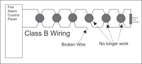
How Does Conventional Class A Fire Alarm Wiring Work
Nfpa S 7 Classes Of Fire Alarm Paths

Domestic Electric Circuit Diagram Wires Fuse Class 10 Physics

Power Amplifier Circuit Diagram Amplifier Circuit Diagram Circuit Diagram

Cbse Ncert Notes Class 10 Physics Magnetic Effects Of Electric Current

Wiring Diagram Electrical Engineering Electricity Electrical Components
0 24 Volt 2 Amp Bench Top Power Supply Make Power Supply Analog Circuits Power

Mercedes W124 Wiring Diagrams Car Electrical Wiring Diagram In 2021 Mercedes W124 Electrical Wiring Diagram Mercedes

Pin On Wiring Diagram
Https Afaa Ne Org Pdfs Afaa Ne Firealarmwiring Pdf

Mercedes Vito Wiring Diagram Mercedes Benz Wiring Diagrams Mercedes Benz W124 230e Wiring Diagram Kfz B Klasse

Pin Di Test
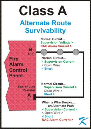
How Does Conventional Class A Fire Alarm Wiring Work

Wiring Diagram Rj45 To Db9 Serial Port Usb Pinout Inside Diagrams Throughout Serial Port Usb Usb Cable
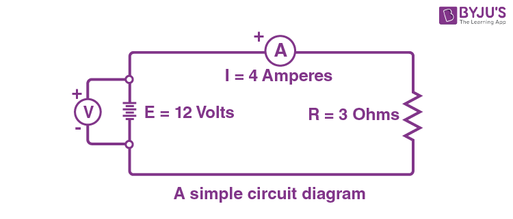
Circuit Diagram And Its Components Explanation With Circuit Symbols

Fire Alarms Jules Bartow Communications Security In The Vein


