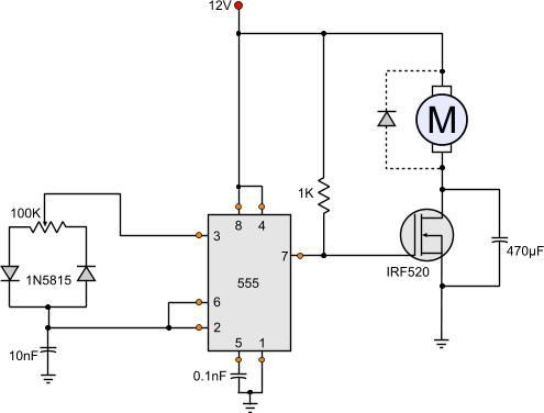
Motor starter control circuit diagram electrical a2z. Complete circuit diagram for the motor controller along with the parts list has been included here.

3 Phase To 1 Phase Wiring Diagram Electrical Circuit Diagram Electrical Diagram Circuit Diagram
Circuit Diagram of DC Series Motor DC Series Motor Circuit Diagram.

Circuit diagram motor. Use power transistors as chances of their damage is less in case of a short circuit due to the heat sink attached to them. Two Speeds One Direction Three Phase Motor Connection Power and Control Diagrams. Run wires from vfd to.
Motor contactor or starter coils are typically designated by the letter M in ladder logic diagrams. Sensorless bldc motor controller using pic18f4550 microcontroller. A normal DC motor as shown below draws 250mA current.
To meet the requirement of low inertia dc servo motors are designed with large length-to-diameter ratio for their. Make sure you have the properly size circuit breaker rated for your amps and vfd. A DC Motor having both shunt and series field windings is called a Compound Motor.
If you want to know what is dc series motor how it works and how its circuit diagram is made then this post may be important for you. Stepper Motor Driver Circuit. In this post Circuit Diagram of DC Series Motor we have shown you about dc series motor.
CD4094B 6N135 ISOLATED UNIPOLAR STEPPER MOTOR DRIVER SCHEMATIC CIRCUIT DIAGRAM. Three Phase Motor Connection Reverse and Forward Power and Control wiring diagrams. Set of 2 op-amps two reference pots ref pot.
Vm is the power supply for motor and its value depends on the motors voltage rating. Ics like 555 timer atmega16 microcontroller 74. ON OFF Three-Phase Motor Connection Power Control Schematic and Wiring Diagrams.
Now as shown in the circuit diagram the 555 circuit here is to generate clock or the square wave. Switching circuit for a permanent magnet dc motor by alex boatman senior project electrical engineering department california polytechnic state university. Make sure everything is correctly sized and accounted for.
We have more Motor Control circuits that you may like to read please take a look below. Except some minor differences in constructional features a dc servo motor is essentially an ordinary dc motor usually shunt. Continuous motor operation with a momentary start switch is possible if a normally-open seal-in contact from the contactor is connected in parallel with the start switch so that once the contactor is energized it maintains power to itself and keeps itself latched on.
All Circuit Diagram Electrical Circuit Diagram. Motor starter control circuit diagram in this guide you will learn virtually how control circuit diagrams are created for motor starters. In a cumulative compound motor the flux produced by both the windings is in the.
D880 transistor has a max collector current rating of 3A. Basic DC Motor Circuits. The connection diagram of the compound motor is shown below.
Ask your students to identify any motor control circuit diagrams theyve already seen as being across-the-line If there are no convenient motor control circuit diagrams available for illustration you may want to ask a student to draw an across-the-line starter circuit on the whiteboard for everyone to see. Admin August 10 2020. The compound motor is further subdivided as Cumulative Compound Motor and Differential Compound Motor.
Circuit Diagram is a free application for making electronic circuit diagrams and exporting them as images. PWM Motor Speed Controller Circuit. The electric motor operated by dc is called dc motor.
2 the control line and the main circuit cable laying. Stepper Motor Driver Circuit Diagram and Explanation. Wiring vfd motor control circuit diagram.
Connect or do wiring as per vfd side drawing. In this topic you study DC Servo motor Theory Circuit Diagram Types Characteristics Applications. The parallel port of the computer using the stepper motor to control a circuit data inputs 6N135 opto kublor is.
Normal dc gear head motors requires current greater than 250ma. Design circuits online in your browser or using the desktop application. It must be greater than the maximum current drawn by your motor.
The frequency of clock generation in this case cannot be kept constant so we need to get variable speed for the stepper motor. Three Phase Slip Ring Rotor Starter Control Power Diagrams. The figure shows the circuit diagram of two stage stepper motor driver.

555 Dc Motor Speed Control Motor Speed Circuit Diagram Electronic Circuit Projects

Dc Motor Speed Controller Circuit Using Ne555 Circuit Diagram Electrical Circuit Diagram Electronic Circuit Projects

Wiring Diagram For 220 Volt Single Phase Motor Http Bookingritzcarlton Info Wiring Diagram For 2 Electrical Diagram Electric Motor Electrical Wiring Diagram

Wiring Diagram For 220 Volt Single Phase Motor Http Bookingritzcarlton Info Wiring Diagram For 220 V Ac Capacitor Electrical Circuit Diagram Circuit Diagram

Stepper Motor Controller Using Tda2030 Schematic Design Stepper Motor Circuit Diagram Electronic Schematics

3 Phase Motor Wiring Diagrams Non Stop Engineering Electrical Circuit Diagram Electrical Wiring Colours Electrical Wiring Diagram

Full Voltage Single Phase Motors Electricity Line Diagram Electrical Diagram

Schematic Diagram Stepper Motor Wiring Schematic And Wiring Diagram Stepper Motor Arduino Stepper Electronic Circuit Projects

Schematic Of The Ac Motor Controller Circuit Diagram Motor Speed Motor

Universal Motor Speed Control Motor Control Circuits Universal Motor Motor Speed Motor

Schematic Diagram Stepper Motor Wiring Schematic And Wiring Diagram Electrical Wiring Diagram Electric Motor Motor

10 Electric Motor Star Delta Wiring Diagram Wiring Diagram Wiringg Net Electrical Circuit Diagram Electrical Wiring Diagram Electrical Diagram

Wiring Diagram For Single Phase Motor In 2021 Car Audio Capacitor Capacitor Electrical Circuit Diagram

Star Delta Motor Connection Diagram Elec Eng World Electrical Wiring Diagram Electrical Projects Electrical Engineering Books

Electrical Engineering World Wiring A Motor Control Circuit Electrical Circuit Diagram Electrical Diagram Electrical Wiring Diagram

Electrical Blog Ac Motor Control Circuit Electronic Engineering Motor Electrical Circuit Diagram

12 Volt Dc Motor Speed Controller Motor Speed Circuit Diagram Electronic Circuit Projects

