How To Repair Bmw E90 2011 Frm Module By Launch X431 Pro Obdii365. Globalsat Br-355 Vhf Wiring Diagram.

3 Phase To 1 Phase Wiring Diagram Electrical Circuit Diagram Electrical Diagram Circuit Diagram
The box must have a minimum depth of 218.

Fcm-1 wiring diagram. Adjustable Fan Relay Wiring Diagram. Having car problems can be very stressful. Citroen Synergie Wiring Diagram.
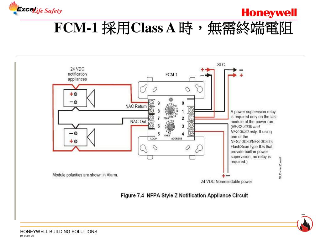
Click the diagram below to view a high resolution copy. A wiring diagram is often used to troubleshoot problems and to make positive that all the associates have been made and that whatever is present. Speaker and audiblevisual applications may be wired for Class B or A Style Y or Z.
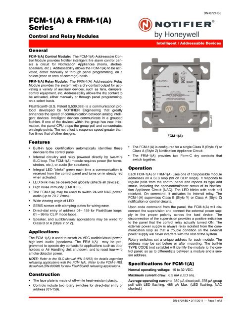
Ł The FRM-1A provides two Form-C dry contacts that switch together. Wide viewing angle of LED. The FCM-1 mounts directly to 4 square electrical boxes see Figure 2A.
Install module wiring in accordance with the job drawings and appropri-ate wiring diagrams. 5 for FRM-1 GENERAL FCM-1 Control Module The FCM-1 Addressable Control Module provides the NOTIFIER AFC-600 control panel for a circuit of Notification Appliances horns strobes speakers etc or to monitor a telephone circuit. The FCM-1A is configured for a single Class B Style Y or Class A Style Z Notification Appliance Circuit.
Typical wiring for speaker supervision and switching NFPA Style Y. The barrier must be inserted into a 4x4x21 8 junction box and the control module must be placed into the barrier and attached to the junction box Figure 2A. Operation Each FCM-1A or FRM-1A uses one of 159 possible module addresses on a.
Install module wiring in accordance with the job drawings and. The FRM-1A provides two Form-C dry contacts that switch together. A wiring diagram is a simplified conventional pictorial representation of an electric circuit.
Ł The FCM-1A is configured for a single Class B Style Y or Class A Style Z Notification Appliance Circuit. Typical fault-tolerant notification appliance circuit con-figuration NFPA Style Z. Sony Cdx-4000x Wiring Diagram.
Fcm 1 Rel Wiring Diagram wiring diagram is a simplified customary pictorial representation of an electrical circuit. Direct-dial entry of address 01 159 for FlashScan loops 01 99 for CLIP mode loops. The FCM-1 has two pairs of output termination points available for fault-tolerant wiring and a panel-controlled LED indicator.
Wiring Diagram For Dry Contact Relay. Notifier Wiring Diagram Shunt Trip Schematic Shunt Trip Fire Alarm All wiring must conform to applicable local codes ordi. Honeywell Rth2300b Wiring Diagram.
Typical notification appliance circuit configuration NFPA Style Y. 128976 Adc Dryer Dsl Module Wiring Diagram. 1981 Yamaha Virago 750 Wiring Diagram.
The fcm 1 rel has two pairs of output termination points available for fault tolerant wiring and a panel controlled led indicator. Bmw E90 Frm Wiring Diagram. April 13th 2019 - Variety of notifier fcm 1 wiring diagram A wiring diagram is a simplified conventional pictorial representation of an electric circuit It reveals the parts of the circuit as streamlined forms and the power as well as signal links in between the tools.
Analog Time Switch Fm1 Quartz Wiring Diagram. Located on the rear left side of the engine compartment the relays and fuses inside are sometimes vulnerable to corrosion and failure. Fcm 1a installation document i56 1169.
SEMS screws with clamping plates for wiring ease. Install module wiring in accordance with the job drawings and appropriate wiring diagrams. Notifier Frm 1 Wiring Diagram Unequalled Fcm 1 Rel Wiring Diagram.
Variety of notifier fcm 1 wiring diagram. Set the address on the module per job drawings. 5 for frm 1 general fcm 1 control module the fcm 1 addressable control module provides notifier intelligent control pan els a circuit for notification appliances horns strobes speak ers etc or to monitor a telephone circuit.
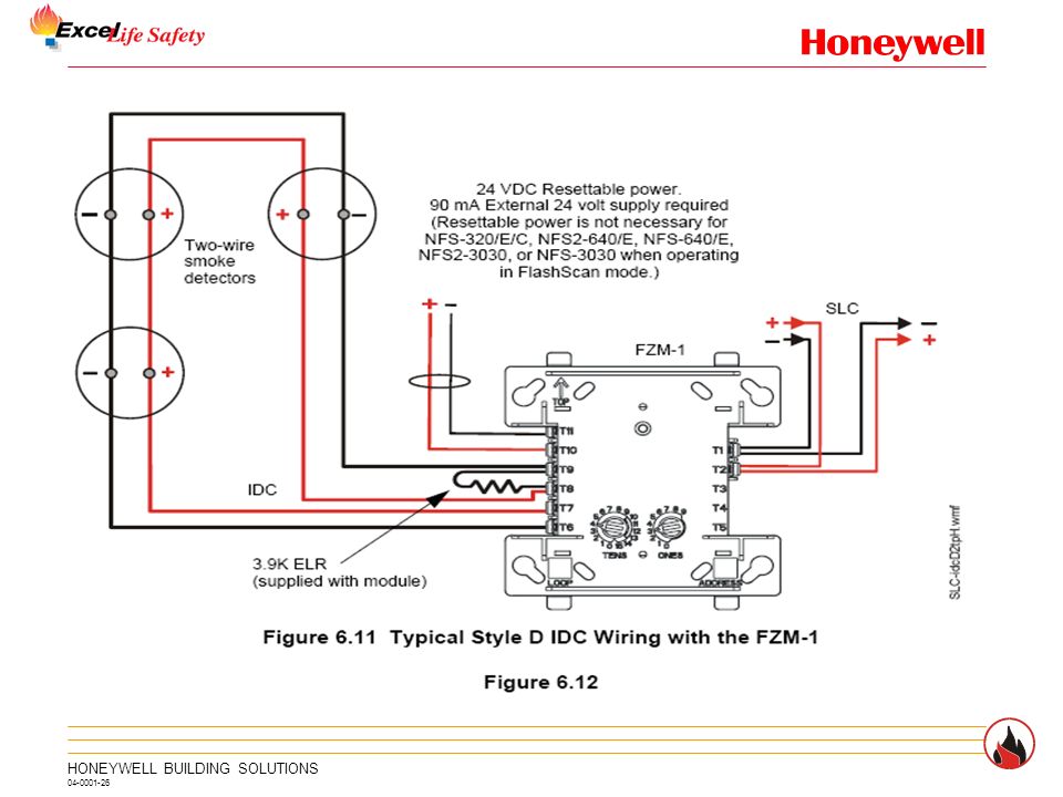
It reveals the parts of the circuit as streamlined forms and the power as well as signal links in between the tools. Rib Wire Diagram Wiring Diagram. The power-limited wiring must be placed into the isolated quadrant of the module barrier Figure 2B.
Operation Each FCM-1A or FRM-1A uses one of 159 possible module addresses. Kk2 Wiring Diagram. When you employ your finger or perhaps the actual circuit along with your eyes its easy to mistrace the circuit.
Replacing ramps 1 4 with mks gen 1 4. The next item you will notice on a vw wiring schematic is a number size assigned to every wire. Notifier Fcm 1 Wiring Diagram Effectively read a cabling diagram one offers to know how the particular components inside the method operate.
For example if a module is usually powered up and it sends out a signal of 50 percent the voltage and the technician does not know this he would think he has a problem as he or she would expect a new 12V signal. Surface mounted electrical boxes SMB500 are available. The following wiring diagrams are provided.
Notifier Fcm 1 Wiring Diagram. All wiring must conform to applicable local codes ordi-nances and regulations. The FCM-1 A may be used to switch 24-volt NAC power audio up to 707 Vrms.
Architectural wiring diagrams do its stuff the approximate locations and interconnections of receptacles lighting and enduring electrical facilities in a building. 1978 Ford F600 Wiring Diagram. Notifier fcm 1 wiring diagram.
Interconnecting wire routes may be shown. It shows the components of the circuit as simplified shapes and the gift and signal contacts amongst the devices. When using control modules in nonpower limited applications the CB500 Module.
FCM-1 Module See wiring diagram Fig. Typical fault-tolerant wiring for speaker supervision and switching NFPA Style Z.

Your Wiring Diagrams Source Peugeot 206 Starting Charging Horn In Pleasing Diagram Diagram Peugeot Citroen Cx

Control Dan Relay Module Notifier Bromindo
Ppt Intelligent Control Panel Slc Powerpoint Presentation Free Download Id 6389167

Fcm And Frm Series Manualzz

Ppt Intelligent Control Panel Slc Powerpoint Presentation Free Download Id 6389167
12 Motorcycle Key Switch Diagram Motorcycle Diagram Wiringg Net Electrical Wiring Diagram Ignite Diagram
Fcm 1 A Frm 1 A Series
Notifier Fcm 1 Control Module Tvpn
Fcm 1 Rel Pdf Power Supply Switch


Pin On B W Bowers And Wilkins Service Manuals

Detection And Control Components Ansul Home And Control Components Fcm 1 Control Module Iq 318 Iq 636x 2 Features Built In Type Identification Automatically Identifies These

Intelligent Control Panel Slc Ppt Video Online Download

Gm 1 Wire Alternator Diagram Voltage Regulator Electrical Circuit Diagram Alternator
Intelligent Control Panel Slc Ppt Video Online Download

Ppt Intelligent Control Panel Slc Powerpoint Presentation Free Download Id 6389167

Pin On B W Bowers And Wilkins Service Manuals

Intelligent Control Panel Slc Ppt Video Online Download

77 Fresh Pam 1 Relay Wiring Diagram Relay Electromagnet Diagram
Fcm 1 Rel Pdf Power Supply Switch


