It offers great flexibility compared with a traditional pencil and paper drawing as design changes can be incorporated and errors corrected quickly and easily. OrCAD Capture prompts you for the name of the new LOGIC CIRCUIT schematic page.
Circuit Design Software Free Download Tutorials Autodesk
Creating the LOGIC Circuit Schematic 1.
How to draw schematic circuit diagram in orcad. Entering the Schematic before you will be able to work through this section. Search and Place Parts. Select Draw Memo Arrow There are several other ways to perform this.
Add Libraries and Parts. This is a modal window. Blow up symbols to view detailed drawings of components.
Take a single large schematic sheet containing your entire circuit and break it up into multiple sheets. In this video learn how quickly you can create designs in OrCAD Capture Cloud using Arrow Reference Designs search for HELP options and where to find easy to use shortcut featrues. OrCAD Capture Cloud- Drawing a schematic.
Regardless schematics should be neat and properly drawn for a given purpose. Download the latest version of OrCAD-powered by OrCAD Capture PSpice Simulation Signal Analysis and Allegro Layout - and try it for yourself. With OrCAD Capture you can.
Earlier designers used to draw the circuit diagram on paper. Beginning of dialog window. Each Operation for Drawing Arrows.
Automatically connect two points in a circuit or bus using the autowire feature. OrCAD Capture schematic entry tool for circuit diagrams is one of the worlds most widely used software for entering and documenting electrical circuits. Neat means that all schematics are drawn and labeled either with a straight edge and templates or preferably with a CAD system or other computed-based drawing package2.
The initial step is to open Schematics using the StartPrograms Pspice StudentSchematics sequence of pop-up menus. Escape will cancel and close the window. It is outstanding how simple and intuitive the design intentions are captured.
At startup the Start Page will be shown. Your drawing and the requirements of individual faculty. You can reference net names and off page connectors to manually follow the logic within your design.
Now they have started to use PCB design tools M-CAD. Each major component of your design gets its own page. Cadence OrCAD PCB Designer with PSpice comprises three main applications.
When Schematics opens your screen will change to the Schematic. Drawing Circuit Diagrams with Schematics. The schematic drawing software commonly used by engineers is PADS OrCAD Altium Designer Protel and so on.
Creating a schematic circuit OrCAD Capture CIS Nordcad Systems AS Nordcad AS 2018 45 96 31 56 99 47 21 55 28 28- R2 supportnordcaddk supportnordcadno Page 2 of 11 2. The sequence to run the simulations involves setting the Simulation Profile for the required simulation type and then running. On the other.
Properly drawn will be discussed more below. CONSTRUCTING AND SIMULATING A DC CIRCUIT I. Lets draw the simple dc circuit in Figure 2 using Schematics.
You can place an image of your block diagram. The following will explain each operation for drawing an arrow. Click on the LOGIC Circuit block symbol click right and select Descend Hierarchy.
Start a new project by selecting File - New - Project from the menu in the OrCAD Capture. Start the Orcad schematic capture program Start - Programs - OrCad 157 Demo - Capture CIS Demo. Via the navigation window the different pages of the.
To ensure layout reliability as well as avoid manufacturing issues your schematic. In practical engineering applications EDA Electronic design automation drawing tools are required to Draw PCB Board Schematic Diagrams. Selecting the Arrow Menu Exiting Arrow Mode Selecting the Arrow Menu.
Perform a Schematic DRC. You will need to complete Section2. Generate smart PDFs and bill of materials.
The following is the operation for exiting Arrow mode. Printed Circuit Boards need to function according to your design requirements and be cost-effective. A schematic diagram is a logical and visual representation of an electrical circuit.
It is the very first step of electronic product design. When you create the new project specify a name. On the Start page select New Project.
This section describes how to use OrCAD Capture-PSpice to simulate the circuit for the Headphone Amplifier example design. The LOGIC CIRCUIT schematic window opens. If youre lucky there will be a topsheet showing all the pages of the circuits.
Observe how OrCAD Capture automatically adds hierarchical port symbols to the new schematic page. Refer to About Executing Menus. Link existing components to your interactive schematic.
Build circuits by linking component symbols together in a schematic diagram. Use Place-Picture and choose the format type thats compatible. OrCAD Capture uses flat or hierarchical circuit diagrams.
Redwire over 5 years ago. Start a Schematic Project. If not select Help Start Page.
Capture is used to drawn a circuit on the screen known formally as schematic capture.

What Is A Circuit Schematic Nwes Blog
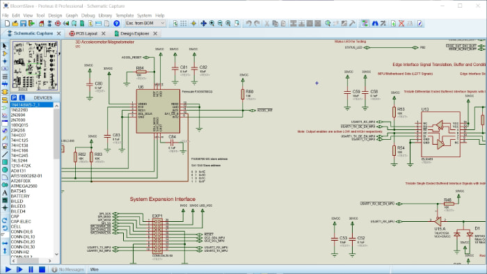
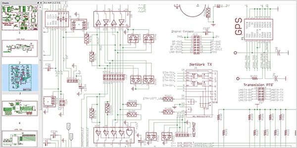
Schematic Capture Software Proteus

Samsung J4 Plus Schemetics Diagram What Is Schemetics Diagram Schematic Diagram Is A Layout Picture Of Mobile Circuite Diagram Samsung Circuit Diagram

Circuit Schematic Electronics Lovers Technology We Love Electronic Circuit Projects Electronics Circuit Circuit

Pin On Technology

Good Tools For Drawing Schematics Circuit Diagram Diagram Design Electrical Circuit Diagram

Simulate Speaker With Equivalent Rlc Circuit Electronics Circuit Circuit Speaker

Top 10 Free Pcb Design Software Gadgetronicx Pcb Design Software Pcb Design Circuit Board Design

A Collection Of Free And Paid Circuit Drawing Softwares Which Can Be Used To Draw Wiring Diagrams Electronics Circuit Diagram Drawing Software Circuit Diagram

Wiring Diagram Symbols Bookingritzcarlton Info Circuit Diagram Electrical Circuit Diagram Circuit Drawing

Pin On Elektronik

Snapeda Component Library Download Eagle And More Schematic Design Electronic Parts Library

High Power Class D Amplifier D4k5 Class D Amplifier Amplifier Circuit Diagram

Arduino Nano Schematic General Electronics Arduino Forum

120w Power Amplifier Power Supply Schematic Design In 2021 Amplifier Power Supply Circuit Subwoofer Amplifier

How You Can Attend Schematic Drawing Software With Minimal Budget Schematic Drawing Software Drawing Software Schematic Drawing Electrical Circuit Diagram

Electronics Rules For Kids Pcb Design Pcb Design Software Circuit Board Design

Electronics Circuit Diagram Schematic Diagram Projects Tutorials Circuit Diagram Circuit Circuit Projects

Free Cellphone Repair Tutorials How To Read Cellphone S Schematic Diagrams Circuit Diagram Diagram Circuit


