Potential difference across an inductor leads the current by 90 in phase while that across a capacitor it lags in phase by 90. When the applied potential is designated as the phase reference then the diagram will be rotated clockwise by φ and φ will be negative for a resultant Inductive Reactance.
Rc Series Circuit Phasor Diagram Impedance Triangle Examples
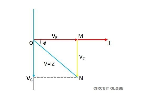
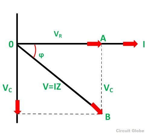
The total supply voltage ET is the vector sum of the resistor and capacitor voltages.
R-c series dc circuit diagram. Practical Significance In the. The large conductors present in the armature and field windings provide the. Suppose three resistors R 1 R 2 and R 3 are connected in series across a voltage source of V quantified as volts as shown in the figure.
Once again the impedance triangle is geometrically. Then VR is along positive x-direction Then VR is along positive x-direction VL along positive y-direction and. Though it is a simple circuit but if you will analyze it your Electrical Engineering basics will be enhanced.
Series and Parallel Circuits 9 3. Use Voltmeter ammeter wattmeter to determine active reactive and apparent power consumed in given RC series circuit draw phasor diagram. Handout on RC Circuits.
The circuit shown in Figures-1 is a simple R-L circuit it has one simple resistor. Phasor diagrams for the series R-L-C circuit shown in Fig. Suppose in a phasor diagram current is taken along the positive x-direction.
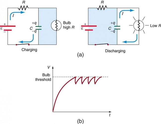
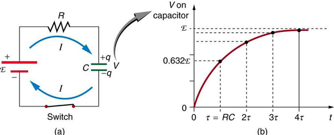
The figure shows the simple R-C circuit in which capacitor C in series with a resistor R that is connected to the DC voltage source via a mechanical switch K. Series DC Circuit Example. 61 at three different frequencies ie.
Digital Electronic Fall 2003 Simplification for time behavior of RC Circuits Before any input change occurs we have a dc circuit problem that is we can use dc circuit analysis to relate the output to the input. In this post Circuit Diagram of DC Series Motor we have shown you about dc series motor. Figure 2 Series RC circuit vector phasor diagram.
The capacitor is initially uncharged. For any frequency lower than resonant frequency f r inductive reactance X L is lesser than the capacitive reactance X C and so the circuit behaves as a capacitive circuit. First we will analyze the circuit when the DC voltage is applied.
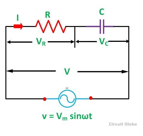
Series and Parallel Circuits In a series circuit. If you want to know what is dc series motor how it works and how its circuit diagram is made then this post may be important for you. Voltage drop V R is in phase with current vector whereas the voltage drop in capacitive reactance V C lags behind the current vector by 90 o since current leads the voltage by 90 o in the pure.
I R 1 R 2 the same current flows through each resistor. The figure below shows a capacitor C in series with a resistor R forming a RC Charging Circuit connected across a DC battery supply Vs via a mechanical switch. Resistor Capacitor AC power source ammeter voltmeter connection wire etc.
Neureuther Version Date 090803 EECS 42 Intro. When we apply an ac voltage to a resistor and capacitor in series as shown in the schematic diagram below the capacitor will constantly charge and discharge as. A f f r b f f r and c f f r with L and C kept constant are shown in Figs.
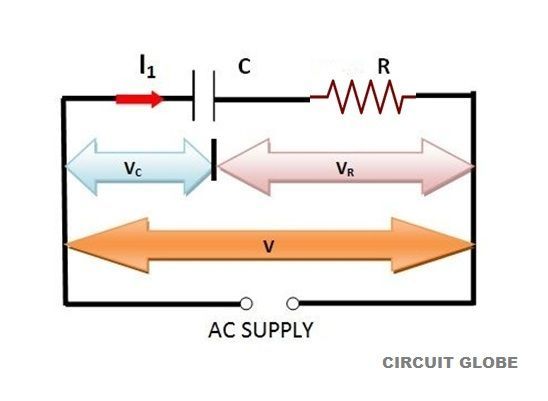
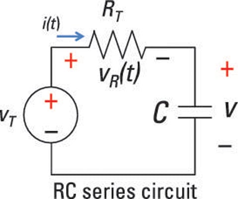
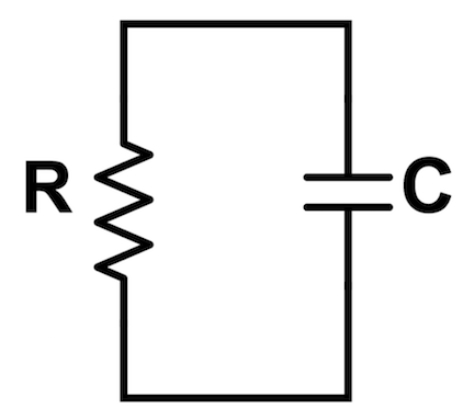
The current at t 0 being i application of KVL leads to. A circuit that contains pure resistance R ohms connected in series with a pure capacitor of capacitance C farads is known as RC Series Circuit. Derivation of Transient Response in Series RC circuit having DC.
Hence in the diagram the power dissipated in them are P 1 I2R 1 and P 2 I2R 2 respectively and the total power dissipated is P T I2R 1 R 2 By Ohms law the voltage source is V I. DC Series Motor Circuit Diagram. RC Circuit Charging R-C CHARGING CIRCUIT.
At time zero when the switch is first closed the capacitor gradually charges up through the resistor until the voltage across it reaches the supply voltage of the battery. Example A 45 V rms 1000 rads-1 supply is connected in series with a 50R6 resistor and a practical inductor which has 40m inductance and 30R resistance combined. In an RC series circuit a pure resistance R is connected in series with a pure capacitor CTo draw the phasor diagram of RC series circuit the current I RMS value is taken as reference vector.
When voltage is applied current flows from power supply terminals through the series winding and armature winding. Let current I quantified as Ampere flow through the series circuit. The resistance R and capacitive reactance XC are 90 degrees out of phase with each other and this forms the impedance triangle shown in Figure 3.
To design Series RC circuit and find out the current flowing thorugh each component. Now according to Ohms law The voltage drop across resistor R 1 V 1 IR 1. In a series motor electric power is supplied between one end of the series field windings and one end of the armature.
Use Voltmeter ammeter wattmeter to determine active reactive and apparent power consumed in given R-C series circuit draw phasor diagram. We call the time period during which the output. 62 a b and c respectively.
The RC Series circuit is shown in the figure below. A sinusoidal voltage is applied and current I flows through the resistance R and the capacitance C of the circuit. Voltage V be applied at t0 by closing a switch S in series R-C circuit figure 1.
Dc Circuits Containing Resistors And Capacitors Physics

Rc Circuits Direct Current Brilliant Math Science Wiki

Rc Circuit Time Constant Charging Discharging Of Capacitor Electrical Academia
What Is An Rc Circuit Circuit Globe
What Is An Rc Circuit Circuit Globe
Analyze A Series Rc Circuit Using A Differential Equation Dummies

Rc Circuit Analysis Series Parallel Explained In Plain English Electrical4u
Rc Circuits Boundless Physics
Rc Circuits Direct Current Brilliant Math Science Wiki
What Is Rc Series Circuit Phasor Diagram And Power Curve Circuit Globe
Application Of Odes 6 Series Rc Circuit

Rc Circuit Analysis Series Parallel Explained In Plain English Electrical4u
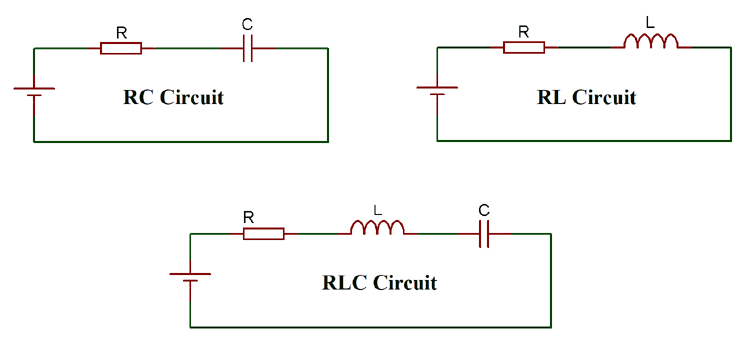
Rc Rl And Rlc Circuit Basic Principle And Circuit Explanations
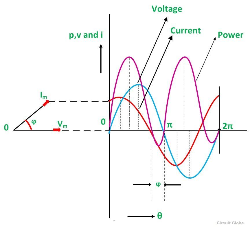
What Is Rc Series Circuit Phasor Diagram And Power Curve Circuit Globe
Rc Circuits Direct Current Brilliant Math Science Wiki
Parallel Rc Circuit Phasor Diagram Impedance Power Examples
What Is Rc Series Circuit Phasor Diagram And Power Curve Circuit Globe

Rc Series Circuit Phasor Diagram Impedance Triangle Examples

Rc Rl And Rlc Circuit Basic Principle And Circuit Explanations


